
How to use generated state machines in no_std Rust firmware (STM32 Nucleo and QEMU)#
Most state machines in embedded Rust are written by hand as an enum and a match. That works
well until the machine grows a hierarchy: a state that contains other states, entry and exit code
that must run in the right order, a “go to failsafe from anywhere” transition. Every new
transition becomes a small refactoring. And if the machine was drawn in a modelling tool first,
the diagram and the code drift apart after a few iterations; under time pressure, nobody brings
them back in sync.
This page takes the other route. The machine is drawn as a UML state diagram, and the Rust code is generated 100% from it. The example is deliberately small, a blinking LED with a failsafe state, but it has the features that make hand-written machines tedious: two composite states, entry code, and transitions that leave a whole group of states.
The machine#
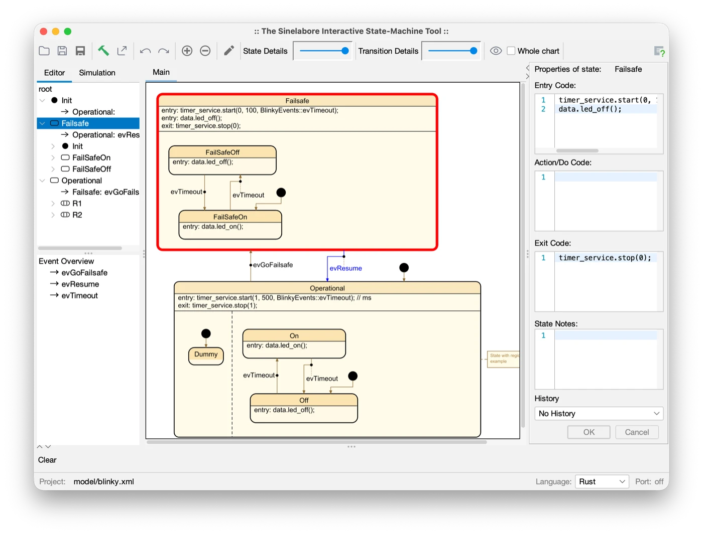
The picture shows the machine in SinelaboreRT’s built-in editor. It uses timers, a state hierarchy and regions to show some of what the tool offers. Here is a quick summary of how it works:
Operationalblinks the LED slowly. Its entry code starts timer 1 at 500 ms. It has two regions:R1, whereOffandOnswitch the LED and alternate onevTimeout, andR2, which only holds aDummystate to show a second region.evGoFailsafe, sent when the failsafe input pin goes low, leavesOperationalfrom either inner state.Failsafeblinks fast: its entry code starts a 100 ms timer, and inside itFailSafeOnandFailSafeOffalternate on the sameevTimeout.evResumeleavesFailsafefrom either inner state and returns toOperational, which starts again inOff.
The same event, evTimeout, does something different in each composite state; the hierarchy
decides which transition takes it.
The actions are written in Rust in the diagram, for example the entry code of On:
data.led_on();data and timer_service are the two parameters every generated state handler takes. Their types
are defined in codegen.cfg:
RustDataType = crate::Board
RustTimerServiceType = crate::Ticker<BlinkyEvents, { crate::TIMER_SLOTS }>
Generating the code#
java -cp codegen.jar codegen.Main -p ssc -l rust -o src/fsm/blinky model/blinky.xmlBefore writing code, the generator checks the model, for example for states that cannot be
reached or left. The result is one file, src/fsm/blinky.rs. The interesting part is the
event handler:
pub fn handle_event(
    &mut self,
    ev: BlinkyEvents,
    data: &mut BlinkyData,
    timer_service: &mut BlinkyTimerService,
) -> BlinkyStep
and inside it, plain nested matches:
BlinkyStates::Off => {
    if ev == BlinkyEvents::evTimeout {
        // Transition from Off to On
        ev_consumed = BlinkyStep::Taken;

        // OnEntry code of state On
        data.led_on();

        // adjust state variables
        self.state_r1 = BlinkyStates::On;
    }
}
Operational calls both regions first. Only an event they ignore is handled by the parent state itself:
ev_consumed = ev_consumed.max(self.blinky_r1(ev, data, timer_service));
ev_consumed = ev_consumed.max(self.blinky_r2(ev, data, timer_service));

if ev_consumed == BlinkyStep::Ignored {
    if ev == BlinkyEvents::evGoFailsafe {
        // Transition from Operational to Failsafe
        ev_consumed = BlinkyStep::Taken;

        timer_service.stop(1);

        // OnEntry code of state Failsafe
        timer_service.start(0, 100, BlinkyEvents::evTimeout);
        data.led_off();
        data.led_on();
        self.state = BlinkyStates::Failsafe; // Default in entry chain
        self.state_failsafe = BlinkyStates::FailSafeOn; // Default in entry chain
    }
}
What the generated file is, and is not:
- It uses
coreonly: nostd, no allocation, no trait objects, nounsafe. It compiles in a#![no_std]crate as is. - The machine is a small
structof enum fields. - One event is handled to completion per call (run-to-completion). The return value says whether a transition was taken.
- States and events derive
Debug,Clone,Copy,PartialEq,EqandHash, and haveas_str()and aDisplayimplementation, which is handy for logging.
Connecting it to the board#
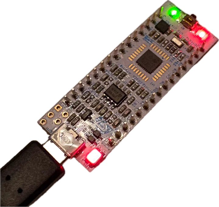
The NUCLEO-L432KC running the blinker. The green LED is the user LED LD3, which the machine switches; the red ones belong to the on-board ST-Link and the power supply.
The firmware supplies Board. On a NUCLEO-L432KC (STM32L432KC, a Cortex-M4) the user LED LD3 sits on PB3:
pub struct Board {
    led: PB3<Output<PushPull>>,
}

impl Board {
    pub fn led_on(&mut self) {
        self.led.set_high();
    }
    pub fn led_off(&mut self) {
        self.led.set_low();
    }
}
Ticker (src/ticker.rs) is a simple software timer written for this example. It reserves TIMER_SLOTS timers, and the diagram
addresses them by id. Id 1 is the 500 ms blink, id 0 the 100 ms one. start stores the event the slot will fire,
stop disarms that slot, and poll reports one event per slot whose period elapsed:
pub const TIMER_SLOTS: usize = 10;

impl<E: Copy, const N: usize> Ticker<E, N> {
    pub fn start(&mut self, id: usize, period_ms: u32, event: E) { /* ... */ }
    pub fn stop(&mut self, id: usize) { /* ... */ }
    pub fn poll(&mut self, elapsed_ms: u32) -> [Option<E>; N] { /* ... */ }
}
The main loop does not decide that a timeout means evTimeout. It forwards whatever poll returns. A wire from pin A0 (PA0) to GND puts the machine into Failsafe; removing it resumes:
let mut machine = Blinky::default();
machine.initialize(&mut board, &mut ticker);

let mut failsafe = false;
loop {
    let wanted = failsafe_pin.is_low();
    if wanted != failsafe {
        let ev = if wanted { evGoFailsafe } else { evResume };
        machine.handle_event(ev, &mut board, &mut ticker);
        failsafe = wanted;
    }
    delay.delay_ms(10_u32);
    for ev in ticker.poll(10).into_iter().flatten() {
        machine.handle_event(ev, &mut board, &mut ticker);
    }
}
The complete firmware (with memory.x and a probe-rs runner) is in
nucleo-l432kc. The board’s built-in ST-Link flashes it over USB: cargo run --release. The release build is 4.4 KB, generated machine and HAL included. Another board only needs its own Board and main loop.
No board? Run it in QEMU#
QEMU emulates a Cortex-M3 board, the LM3S6965EVB (Rust target thumbv7m-none-eabi, a close
relative of the Nucleo’s Cortex-M4).
qemu runs the
unchanged generated file there, in real time:
the SysTick timer interrupts every 10 ms, the main loop sleeps with wfi in between, and it
forwards every event poll returns. The Board prints over
semihosting, and a schedule stands in for the failsafe wire: on at 1250 ms, off at 1750 ms.
static TICKS: AtomicU32 = AtomicU32::new(0);

#[exception]
fn SysTick() {
    TICKS.fetch_add(1, Ordering::Relaxed);
}
git clone https://github.com/sinelabore/examples.git
cd examples/Embedded/rust/blinky/qemu
rustup target add thumbv7m-none-eabi
cargo run 0 ms initialize
timer 500 ms
LED off
500 ms evTimeout
LED on
-> On
-> Dummy
1000 ms evTimeout
LED off
-> Off
-> Dummy
1250 ms evGoFailsafe
timer stopped
timer 100 ms
LED off
LED on
-> FailSafeOn
1350 ms evTimeout
LED off
-> FailSafeOff
1450 ms evTimeout
LED on
-> FailSafeOn
...
1750 ms evResume
timer stopped
timer 500 ms
LED off
-> Off
-> Dummy
2250 ms evTimeout
LED on
-> On
-> DummyThe runner in
.cargo/config.toml starts qemu-system-arm -machine lm3s6965evb with the built binary; the run
takes 3 s of wall-clock time.
Testing it on the host#
Because the generated code only sees Board and Ticker, the same file also compiles for the
PC. In src/lib.rs, Board sets a flag instead of a GPIO pin, so ordinary #[test] functions
can drive the machine and check it without any hardware.
Beyond the blinker#
The same generator handles what makes larger machines hard to write by hand:
- deep and shallow history, choices, and conditional transitions;
- regions, each with its own handler (the blinker already has two inside
Operational); - events that carry data: the fields of an event become an enum variant, bound by name in guards and actions;
- test routes that take every transition at least once (
-c); - a built-in editor to draw, check and simulate the model, if you do not use a UML tool (Enterprise Architect, MagicDraw, Cadifra and others are supported).
The editor can also show which states the firmware is in while it runs. The firmware sends its innermost active states, for example over the serial port to a small forwarder on the PC, and the diagram highlights them. The generated innermost_active_states() returns them, one per active region, without allocating, so the report is a short loop:
write!(uart, "from=blinky;state=").ok();
for (i, state) in machine.innermost_active_states().enumerate() {
    write!(uart, "{}{}", if i > 0 { "," } else { "" }, state).ok();
}
writeln!(uart).ok();
Try it#
The complete example (model, generated code, host stand-in, NUCLEO-L432KC firmware and the QEMU variant) is on GitHub: Embedded/rust/blinky. The generated file is checked in, so it builds and runs without the code generator. To change the model and generate the code yourself, get the code generator from the download page.
All options of the Rust code generation are described on the Rust backend page. A blinker with a failsafe in C, on an STM32 with CubeMX and CMSIS-RTOS, is described in How to use state machines generated by Sinelabore with STM CubeMX.
Questions and criticism are welcome at info@sinelabore.com, especially about the shape of the generated code: what would you change to make it fit your firmware better?