DCF77 Radio Clock#
In this example, a decoder for the DCF77 standard-frequency radio signal is realized based on two cooperating state machines. You will learn how to use the features of the code generator:
- Machines based on conditional and event-based triggers
- Adding your own variables to the machine instance data
- Adding custom code to the generated state machine file
- Using a custom event type that includes both event and data
DCF77 Basics#
The transmitter is located near Frankfurt in Germany and continuously transmits a 77.5 kHz signal that encodes local time using amplitude and phase modulation. The sender is controlled by the high-precision atomic clocks of the German institute of standards, the Physikalisch-Technische Bundesanstalt in Braunschweig. The signal can be received almost everywhere in central Europe with very simple and cheap receivers. A short description of the motivation and encoding of the DCF77 signal can be found on Wikipedia.

The DCF77 modulation reduces the signal amplitude for 0.1 seconds (short pulse, 0 bit) or 0.2 seconds (long pulse, 1 bit) at the beginning of each second, allowing transmission of 1 bit of data per second. A simple BCD encoding scheme is used to transmit hours, minutes, days, and date information for the next minute. The encoding scheme of the time information transmitted with DCF77 is described here.
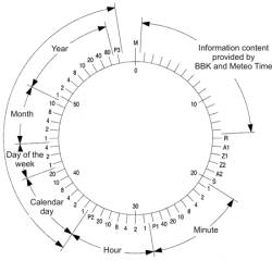
To allow synchronization with the continuously sent signal, no pulse is sent during the 59th second, so that the start of the next pulse exactly marks the beginning of the minute.
The receiver application is split into two separate state machines.
The pulse detection state machine#
The pulse detection state machine runs within a cyclic timer interrupt service routine. It initially searches for the minute start M and then detects long and short pulses. This state machine runs cyclically and does not need any external triggers (events). Instead, all state transitions are based on the DCF77 output signal level. We call such state machines conditional machines because state transitions are based on input conditions or variable values. The transition types are described here in the section about transitions.
The CPU is normally in low-power state. But when a pulse or minute start is detected, the decoder machine wakes up the CPU.
#pragma vector=TIMERA0_VECTOR
__interrupt void Timer_A0(void){

    // set debug output high if pin of dcf77 signal is high
    if((P1IN & 0x01) == 1U) P1OUT |= 0x04;
    else P1OUT &= ~(0x04);                  // clr debug pin

    P1OUT |= 0x08;                          // set debug len of irq

    dcf77_irq(&irqSM);
    if(irqSM.msg==evTick || irqSM.msg==evMinStart){
        // wake up main CPU, got valid pulse
        __bic_SR_register_on_exit(LPM3_bits);
    }

    P1OUT &= ~(0x08);                       // clr debug len of irq
}
The state machine was created with the integrated state diagram editor. A screenshot is shown here. The editor allows creating state machine diagrams very efficiently. A multipart tutorial is available.

The state diagram editor allows directly adding code to various sections of the state machine. In this example, some helper functions and variables were added to the beginning of the state machine file. More details about the offered possibilities can be found in the tutorial part I. In addition, it is also possible to add variables to the state machine instance type. These variables can then be used for data exchange or storing local data. In this example we use this possibility to store several internal variables used for the pulse detection state machine.
The decoder state machine#
The second state machine runs in the endless main loop and executes once if a pulse was detected. Initially it waits for the minute begin. Once found, the state machine processes events coming from the pulse detection machine (in contrast to the conditional state machine above). The first 20 bits contain special information and are ignored. Then once the minute bits arrive, the time and date information is captured and decoded. Finally the clock is set before the cycle starts again.
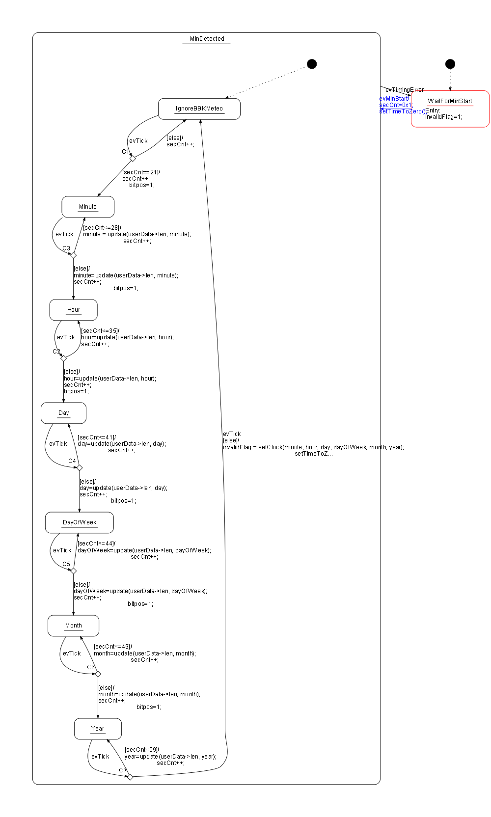
The following code shows the main loop, which runs only if a new pulse is available for processing. The state machine uses a custom event type (see below), which is filled before the machine is called. Then low-power mode is entered again.
while(1) {
  _BIS_SR(LPM3_bits + GIE);                 // Enter LPM3
  __no_operation();

  P3OUT |= 0x8;                             // set D2 debug output

  // update event information and call the decoder
  decoderEvt.msg = irqSM.msg;
  decoderEvt.len = irqSM.len;
  decoder(&decoderSM, &decoderEvt);

  P3OUT &= ~(0x8);
}
Event Type#
This example presents another feature of the code generator. The state machine handler can have different signatures. Usually, a pointer to the instance data and the event to process is passed. Here we have defined a custom event type (OWN_DECODER_EVENT_T) that contains not just the event but also data (the length of the detected pulse).
For this state machine handler signature:
void decoder(DECODER_INSTANCEDATA_T *instanceVar, OWN_DECODER_EVENT_T *userData){...the following parameters must be set in the configuration file. Note: the integrated editor has a helper function to find the right parameters for you (Code -> Handler Signature).
UseInstancePointer=yes
HsmFunctionWithEventParameter=yes
InlineChangeToStateCode=yes
HsmFunctionUserDefinedEventParameter=OWN_DECODER_EVENT_T
Debugging Trace#
To better understand the timing of the design, some debug signals are generated in the IRQ handler and main loop. The following figure shows a capture of the generated debug signals:

D0 shows a received DCF77 pulse with a length of 100 ms. D1 shows the duration of the IRQ handler routine. D2 shows the execution time of the main loop. You can see that the CPU can stay in sleep mode most of the time.
Organization of the Code#
Each state machine is in its own folder. Within each folder you will find the state machine model file (*.xml) and the corresponding configuration file. You can open and edit the files easily using the state machine executable (right-click on the file and open with sinelabore.exe). In the tool you can then regenerate the code when needed. In main.c the board is initialized and the state machines are called.
Conclusion#
This tutorial presented how to use conditional and event-based state machines to realize a complete application on a small embedded system. The whole code fits in 2 kB of code and 110 bytes of RAM.
The complete source code and model files are available for download. Feedback is very welcome.