Signal-Forming Function Block Design with State Diagrams#
Nearly every embedded system must handle binary inputs. Device behavior is often influenced by their state. In many cases, however, the raw input signal is not used directly; instead, a preprocessed signal is used, such as:
- Trigger activity on the rising or falling edge of an input signal (
ftrig,rtrig). These blocks are useful for creating an event from a Boolean signal. - Delay the input signal for some time (so-called on-delay)
- Wait until an input signal is switched off again (so-called off-delay)
- Combine both behaviors above (on/off delay)
- Provide a pause input to pause the timing condition of the signals above
- Provide an option to reset a running timer
- Shape an input signal, i.e. create a pulse of defined length independent of the input signal length
- Debounce inputs
There are many more such functions. You may have come across them in your own practice. The relevance of well-defined binary signal handling is also shown by industrial standards such as IEC 61131-3, which defines a set of standard function blocks that form the building blocks of PLC programs. Among others, these function blocks include timers (TON, TOFF), counters, bistables (SR, RS), edge detectors (RTRIG, FTRIG), and more.
What you learn in this tutorial#
This article explains how to use state machines to create a reusable function block library for control signal forming. It covers:
- how to use conditions to trigger state transitions in your state machine
- how to benefit from adding attributes to a stateful class
In another example, you can learn how to create a PLCOpen safety function block using the same concept.
What are conditional events?#
The code generator supports two basic modes of operation that should not be mixed. In one mode, it processes events: a transition is taken only when an event is present. Events are typically sent to the state machine through an event queue. In the other mode, transitions are triggered by Boolean conditions: if a condition is true, a state change occurs. The latter mode is useful for processing binary signals, as shown in this example. In this case, the state machine runs without dedicated events and uses Boolean state conditions to trigger transitions.
The solution#
It is very useful to have a library of such functions that can be integrated easily into a system design. All functions above require state, so modeling them as state machines is a natural choice. The design presented here is based on Enterprise Architect and uses class attributes to model additional data. These attributes are added to the instance data. They can be used for internal variables and as an external interface. We use both in the examples below. Let’s start with the ftrig and rtrig functions. They do not depend on time and are therefore simpler to model.
Before looking at the state machines, first take a look at the class diagram.

Each function is modeled as a class. The classes include different additional attributes. All of them use binary signals such as q (output) and set. Some also include additional binary signals such as pause and reset, or variables that define delay times. Internal data is also modeled, for example to store elapsed time.
When modeling attributes, it is recommended to define your own data types using UML primitive data types. This helps ensure a consistent set of data types across code that is and is not modeled in UML. The following figure shows the model tree with classes and data type definitions inside a common package.

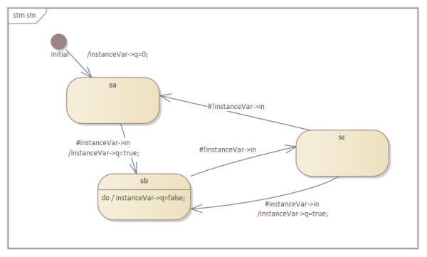
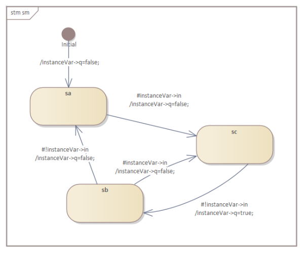
RTRIG and FTRIG functions#
The following two state diagrams show models for the falling-edge (ftrig) and rising-edge (rtrig) functions. No time information is required, only the status of the previous input signal. Conditional triggers are marked with a hash (#) as the first character.
Pulse Function#
The single-pulse function shapes the length of an input signal into a defined pulse length at the output. It requires a notion of time. The implementation uses the system tick to obtain timing information and calculates elapsed time on each call of the state machine.

On/Off Delay with Pause and Reset Inputs#
This function block is the most complex one. It requires several internal variables to store temporary information and two independent time settings. The reset and pause inputs make the function even more flexible.

Generating Code#
To generate code from the state machine model, the following command lines were used (the class path -cp points to the location of codegen.jar):
java -cp "*" codegen.Main -p ea -t "Model:signal_processing:package:on_off" -o ton_toff signalprocessing.xmi
java -cp "*" codegen.Main -p ea -t "Model:signal_processing:package:ftrig" -o ftrig signalprocessing.xmi
java -cp "*" codegen.Main -p ea -t "Model:signal_processing:package:rtrig" -o rtrig signalprocessing.xmi
java -cp "*" codegen.Main -p ea -t "Model:signal_processing:package:single_pulse" -o single_pulse signalprocessing.xmi
clang -l ncurses ton_toff.c main_on_off.c -o ton_toff
clang -l ncurses main_rtrig.c rtrig.c -o rtrig
clang -l ncurses main_ftrig.c ftrig.c -o ftrig
clang -l ncurses main_single_pulse.c single_pulse.c -o single_pulse
The only two additional functions that must be provided are those that deliver elapsed-time information.
uint32_t getSystemMilli() {
    struct timeval now;
    gettimeofday(&now, NULL);
    return now.tv_usec / 1000 + now.tv_sec * 1000;
}

uint32_t getDiffMilli(uint32_t old_milli) {
    uint32_t milli = getSystemMilli();
    uint32_t diff = milli - old_milli;
    // printf("Milli=%d, old_milli=%d Diff=%d", milli, old_milli, diff);
    return diff;
}
That’s all; everything else is generated.
Testing the Implementation#
To test the implementations, test patterns were generated and used to call the state machines. The inputs and outputs of relevant signals were displayed over time using the curses library. Some examples:
ton with pause  tond=500, toffd=0
  Set:___***************_______________
Reset:_________________________________
Pause:_____****________________________
    Q:____________******_______________

ton/toff  tond=300, toffd=800
  Set:__*******___________***__________
Reset:_____________________*___________
Pause:_________________________________
    Q:_____************________________

rtrig testcase 2
Set:___****__*___
  Q:___*_____*___

ftrig testcase 1
Set:___****_*__*_
  Q:_______*_*__*

single pulse false at begin
Set:___*************______*__________
  Q:___***________________***________

Debounce button test
 Input__*__*_**__****************_*_**_*_*___*____*__________
 Out  _____________*************************_________________
 Cnt  0011120120012345678999999997867867564201111120000000000
Final thoughts#
State machines with conditional transitions are a powerful way to model signal-forming functions. The approach shown here makes reuse easier within the same project and across future projects. In addition, the model itself serves as documentation and stays in sync with the implementation. This benefit alone is a strong reason to model your next state-based design and generate the code instead of writing it manually.
If you are interested in the complete code, the model files are available here:
- EA: Enterprise Architect Model file (created with version 16)
- UModel: UModel Model file
- Built-in Editor: Model files for the built-in state diagram editor
Looking forward to receiving your thoughts and ideas for other useful blocks.