Getting started with the PIC16F18446 and State Machines#
This tutorial explains the use of state machines with the PIC16F18446 Curiosity Nano board. It provides 2k of RAM and 16k program memory, more than enough for this small tutorial.
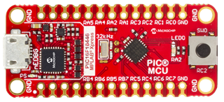
(Source: Microchip)
Install the required software if you want to follow all steps yourself. Otherwise just continue reading.
For this tutorial we will use just the push button and the LED on the board. So you can follow it without any additional hardware required. The LED shall blink all the time. The frequency can be changed from slow to fast by pressing the button. Simple enough, but sufficient to show all the key concepts we are going to use.
The PINs are allocated using the MPLAB X IDE Resource Manager as well as the 4MHz system clock and the 10ms Timer0. I have not used this configurator before, but it is a very convenient way to setup the hardware.
Step 1 - Deciding the system architecture#
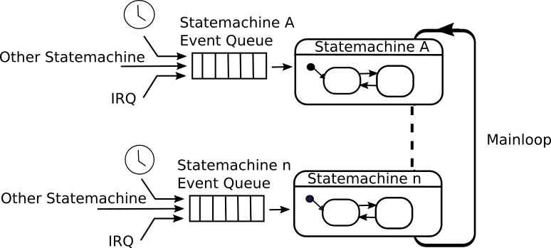
For small systems, e.g. sensor nodes, it is usually sufficient to use a main loop design. The main loop cycles endlessly and waits for events. Events are beneficially stored in an event queue. The queue is filled from timer events, other state machines (cooperating machines), or interrupt handlers. If events are available, the state machine(s) are called from the main loop to process them.
In our little example events are sent from the keyboard interrupt and from a software timer module which is called regularly from the cyclic hardware timer. The following figure shows the system architecture.
The code snippets below show the IRQ handlers and the main loop processing the events.
// cyclic timer interrupt
void TMR0_IRQHandler(void){
    tick(); // if a timer has fired this function stores a timer event in the message queue
}

// keyboard interrupt
void SW0_IRQHandler(void){
    fifoPut(&fifo,evKey);
}

void main(void){
    ...

    while (1)
    {
        do {
            // check if there are one or more events in the queue.
            // if yes, process all events in the state machine
            retVal = fifoGet(&fifo, &bufVal);
            if (retVal != QUEUE_EMPTY) {
                sm(&instData, bufVal);
            }
        } while (retVal != QUEUE_EMPTY);
        __delay_ms(10U);
    }
}
In the library folder (see project tree below) the required timer and fifo files are provided. They can be easily reused also with other controller types.
Step 2 - Realizing the state machine#
So far we have not seen how the state machine looks like. To realize this simple job just two events are required.
- evKey: Indicates that the user pressed the switch
- evTimeout: Indicates that it is time to toggle the LED
For this simple state machine, the editor built into the code generator is sufficient. For more complex machines it is recommended to use an advanced UML modeling tool of your choice. See the list of supported tools. The next figure shows the complete state machine:
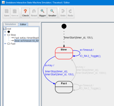
Initially the state machine enters the state Slow. The initial transition triggers the start of the timer with timeout time 10U (10U represents 10 times the base clock of the hardware interrupt, i.e. 100ms). Then the machine waits for further events. Every time event evTimeout occurs there is a self transition and as action the LED is toggled.
In case evKey occurs a state transition from state Slow to state Fast and vice versa is triggered and the timeout time is updated.
Example action code for the transition going from state Slow to state Fast:
timerStop(timer_id);
timerStart(timer_id, 10U);
Step 3 - Integrating the state machine in MPLAB X#
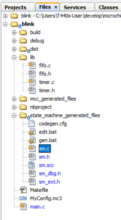
The generated state machine code files can be easily added to the PIC project. It is recommended to create a new folder e.g. called state_machine_generated_files. All state machine related files go in there. sm.scc contains the state machine model. sm.c/h contains the generated state machine code.
The following figure shows the project tree with all generated files.
To conveniently edit the state machine model and generate code from it, two batch files were created.
Call edit.bat to start up the editor. And call gen.bat to generate the code. The generated files start all with the prefix sm_ (see command line). The output when calling gen.bat is shown below.
C:\Users\PM\develop\microchip\blink.X\state_machine_generated_files>java -Djava.ext.dirs=C:\Users\PM\Desktop\sinelaborert\bin\ -jar C:\Users\PM\Desktop\sinelaborert\bin\codegen.jar -p ssc -l cx -o sm sm.scc
Starting robustness tests of state machine ...
State names: ..............
Machine hierarchy: ........
Machine height = 1
Transitions: ..............
Default states: ...........
Final states: .............
Choices: ..................
No. of children in composites: ...
Connectivity of states: ...
The code generator needs a configuration file to set basic parameters. Take a look into the configuration file and read the Manual if the meaning of the parameters is not clear.
Wrapup#
The chosen system architecture with state machines, an event queue and software timers is very powerful. It is proven in practice since many years and used successfully in many projects. Quite complex systems can be built this way and no RTOS is required. It can be expanded easily by adding additional state machines and by using more than one software timer.
Use the example and expand it to learn. To receive a copy just send a mail.