Using State-Machines in Low-Power Embedded Systems#
Introduction#
This example explains how to integrate state machines into deeply embedded low-power systems that should stay in deep-sleep CPU modes as long as possible to save energy.
The CPU in a low-power system is usually only active from time to time to react to events triggered from outside (e.g. a pressed key) or from inside the system (e.g. ADC ready, timer expired). After processing the event, the CPU goes into low-power mode again.
All this is done to keep the batteries running as long as possible. A good example of such a system is a wireless temperature sensor mounted outside the window sending temperature data from time to time to a central display, a monitor attached to a bird to track the flight route, or a bike computer. The longer the batteries last, the better.
Systems that are always powered from an external supply can also benefit from a low-power design. Power consumption is a real buying criterion nowadays.
System Design#
The following example is based on a small MSP430F1232 header board with just 256 bytes of RAM and 8K of program memory. For development, Code Composer Studio from TI was used. In the end, the program needs <2k Flash and 182 bytes RAM incl. stack. The following block diagram shows the controller with its I/O connections.

Figure 1: MSP430F1232 block diagram
To avoid burying the design principles in too much detail, the MCU runs just two state machines fully generated from UML state diagrams. One machine measures the battery voltage every 2 seconds. The other measures the temperature on a cyclic basis using a TMP100 from TI connected via I2C to the MCU. Temperature measurement happens only if the battery voltage is high enough. Otherwise, an LED is pulsed to indicate a low-voltage state (P1.3). The radio part that sends the temperature to a central server was omitted here.
The two state machines that implement the user application are shown in figure 2 below. The state machines were designed with the built-in Java UML editor. To change or extend the functionality, modify the state machines, regenerate the state-machine code, and then compile and link as usual. Changes to I/O port 1 were added to verify the timing with an oscilloscope (see below).
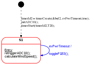
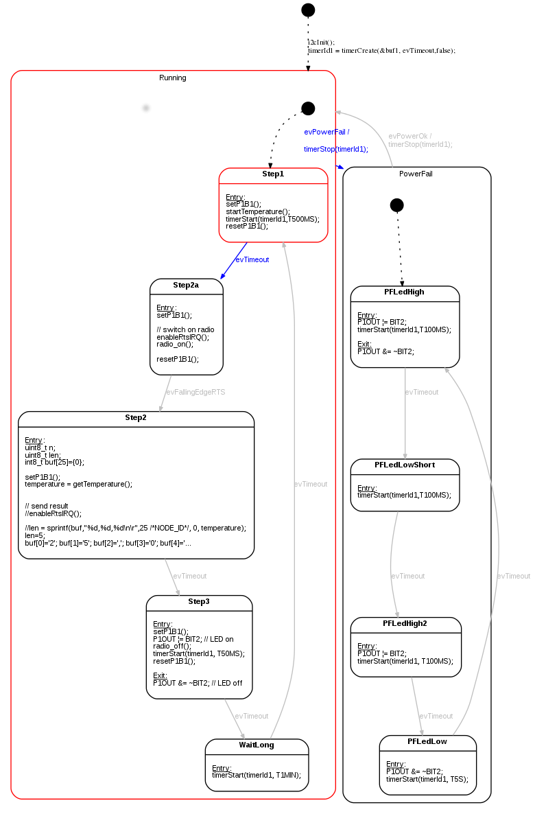
Figure 2: Application logic implemented as state machines. Top: Triggering the voltage measurement with a cyclic timeout. Bottom: Switching between two operation modes depending on supply voltage level. Single-shot timers are used for timing.
Reusable Library Layer#
The design is based on the following library elements that can be reused from project to project:
- A timer abstraction layer provides timers for the user application. The timer abstraction is based on a system tick implemented with hardware
timer Ahere. If a timer has expired, thetick()routine returnstrueand the CPU is woken up. Otherwise, low-power mode is entered again.
__interrupt void Timer_A0(void)
{
  bool retVal;
  P1OUT ^= BIT0;        // toggling bit for debugging
  retVal = tick();    // timer service. Check if any timer has expired

  if(retVal){
    // at least one timeout timer fired.
    // wake up main loop
    __bic_SR_register_on_exit(LPM0_bits);
  }
}
Listing 1: Timer interrupt service routine calling the timer handler tick().
- The user code can create multiple timers and receive time-out events when they expire. During timer creation, the event queue and the timer event must be provided. If a timer expires, this event is stored in the given event queue. The timer implementation can be found in the
libraryfolder in filestimer.candtimer.h. Thetick()function is the core of the timer library and is shown below:
bool tick(void){
  bool timeoutAvailable=false;

  // Iterate over the timers and enqueue
  // timer events once a timeout has happened.
  for(uint8_t i=0; i<MAX_TIMERS; i++){

    if(timers[i].timerStatus==ON){

      timers[i].elapsedTicksSinceStart++;

      if(timers[i].elapsedTicksSinceStart==timers[i].preset){
        // timeout time elapsed.
        timers[i].timerStatus=OFF; // stop timer
        fifoPut(timers[i].rbuf, timers[i].evTimeout); // enqueue timeout event
        timeoutAvailable=true;
      }
    }
  }

  return timeoutAvailable;
}


// starts timer
// Returns either ON if started or OFF if not started (e.g. preset=0)
TIMER_STATE_T timerStart(uint8_t t_id, uint16_t ticks);

// stops timer
void timerStop(uint8_t t_id);

// either returns ON or OFF or PAUSE
TIMER_STATE_T timerStatus(uint8_t t_id);

// set timer timeout in ticks
void timerSet(uint8_t t_id,uint16_t ticks);

// Timer function to be called from the timer irq handler.
// If at least one timer fired the function returns 1. Otherwise 0.
bool tick(void);

// pause timer
void timerPause(uint8_t t_id);

// resume timer
void timerCont(uint8_t t_id);

// Not yet implemented
void timerErase(uint8_t t_id);
Listing 2: The timer interface and the tick handler. The tick handler checks whether any timer has elapsed. In that case, the user-provided event is stored in the corresponding queue.
- A queue service. Queues are used to store events from timers or other event sources in FIFO order. Multiple queues can be created, usually one per state machine. The queue code is available in the
libraryfolder in filesringbuf.candringbuf.h.
typedef struct Buffer {
    uint8_t *data;
    uint8_t mask; // size - 1
    uint8_t read; // index of oldest element
    uint8_t write; // index of field to write to
} FIFO_T;

void fifoInit(FIFO_T * const buffer, uint8_t  * const pByte, uint8_t size);
bool fifoPut(FIFO_T * const buffer, uint8_t byte);
bool fifoGet(FIFO_T  * const buffer, uint8_t * const pByte);
bool fifoPutHead(FIFO_T * const buffer,  uint8_t byte);
bool fifoIsEmpty(const FIFO_T * const buffer);
Listing 3: The queue interface. Multiple queues can exist. A state machine usually has one input queue to pick the next event from.
Weaving the state machines and the library part together#
On top of the minimal abstraction layer (timers, queues) sits the application-specific part. It is implemented as state machines reacting to events. The state machine code is fully generated from the UML state machine diagrams. The main routine initializes the hardware and then enters a main loop that waits in low-power mode. ADC and timer interrupt handlers wake the CPU after they enqueue an event. When it wakes up, the main loop pulls these events out and calls the appropriate state machine with the event as a parameter. See the following code snippet for the implementation details:
/**
 * Main loop initializes the hardware and software
 * and then waits in low power mode until new events
 * are present. Events are then pulled out of the
 * queues and forwarded to the appropriate state-machine.
 */
void main( void )
{
  // Stop watchdog timer to prevent a timeout reset
  WDTCTL = WDTPW + WDTHOLD;

  // initialize timer
  TACCTL0 |= CCIE;                           // CCR0 interrupt enabled
  TACCR0 =  41U;
  TACTL = TASSEL_1 + MC_1 + ID_3;           // SMCLK/8, upmode


  P1OUT &= 0x00U;               // Shut down everything
  P1DIR &= 0x00U;
  P1DIR |= BIT0 + BIT1+BIT2+BIT3;       // set pins to output the rest are input
  P1OUT |= BIT1 + BIT1+BIT2+BIT3;         //Select pull-up mode

  fifoInit(&buf1, buf1data ,sizeof(buf1data)/sizeof(uint8_t));
  fifoInit(&buf2, buf2data ,sizeof(buf2data)/sizeof(uint8_t));

  timerInit();
  init_uart();
  radio_init();
  initWindSensor();

  // run once to init
  toggle(&smToggle, TOGGLE_NO_MSG);
  pwr(&smPwr, PWR_NO_MSG);

  while(1){                      //Loop forever

    uint8_t retVal;
    uint8_t bufVal;

    do{                         // first process all events for task A
      retVal = fifoGet(&buf1, &bufVal);
      if(retVal!=QUEUE_EMPTY){
        toggle(&smToggle, bufVal);
      }
    }while(retVal!=QUEUE_EMPTY);

    do{                        // then all evenets for task B
      retVal = fifoGet(&buf2, &bufVal);
      if(retVal!=QUEUE_EMPTY){
        pwr(&smPwr, bufVal);
      }
    }while(retVal!=QUEUE_EMPTY);
    // more tasks could follow here

    __bis_SR_register(LPM3_bits + GIE);  // Enter low power mode once
    __no_operation();                    // no more events must be processed

  }
}
Listing 4: The main routine waiting in low power mode until events are available. Then these events are forwarded to the state machine handlers.
How to handle longer-lasting tasks#
Execution time for handling events should be as short as possible. Longer-lasting tasks should be split into chunks. Take the temperature measurement as an example. The TMP100 temperature sensor requires about 320ms conversion time according to the datasheet. The MCU should not busy-wait and burn CPU cycles; it should either wait in low-power mode or process other events. You can do this by starting the conversion in one state (Step1), then starting a timer and entering low-power mode. When the timer fires, pick up the conversion result (Step2) and process it further.
Another example is the wake-up procedure of the radio. After leaving low-power mode, it takes a while before the radio is ready. Readiness is signaled by a transition of the RTS pin from high to low. After switching on the radio in state Step2a, we enter low-power mode again. The level change triggers an interrupt and sends the event evFallingEdgeRTS. Now the radio is ready to transmit data.
Object Diagram#
The software design is shown in the next figure as a UML object diagram. You can clearly see how the queues decouple the event sources from the event consumers. The main loop serves as an event dispatcher that is active only when events are available in one of the queues. The main loop can also be used to prioritize one state machine over another or to enforce the order in which state machines run.
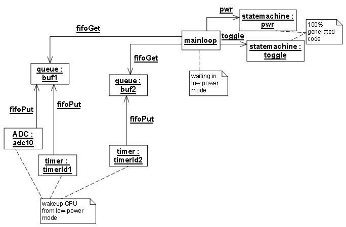
Figure 3: Object diagram of the whole application.
To verify overall system behavior, some output port pins were used as follows:
- The Timer A interrupt routine is shown as
clkin the first line. The port pin is toggled on each interrupt, i.e., every 100 ms. - When the supply voltage drops, the measurement stops (line 2) and the power-fail LED starts flashing (line 4). The
evPowerFailtransition starts from stateRunning. As a result, the temperature measurement cycle can start just as anevPowerFailevent occurs but cannot finish. You can see this in the oscilloscope image: there is only a single pulse. To fix this, let theevPowerFailtransition start from stateStep2. That ensures a measurement cycle always completes before the state changes toPowerFail. - Line 3 shows the timing of the voltage-measurement state machine (cycle of 2 seconds).

Figure 4: Oscilloscope image showing the timing of the whole application. Line 1: system tick. Line 2: timing of the temperature measurement phases (measurement only occurs if the supply voltage is above a defined threshold). Line 3: supply voltage measurement. Line 4: LED output; analog line: battery voltage.
Discussion#
- This article shows the principal concepts for designing low-power embedded systems using state machines, timers, and queues.
- Queues and timers are basic services that are application-independent and can be reused from system to system. Timer resolution and the number of timers and queues can be tuned to optimize memory use.
- The user application is modeled as state machines that receive events from external or internal sources via queues—that is, decoupling is achieved with queues.
- State machine processing time must be short enough that no events are lost and overall response time stays within bounds.
The source code is for demonstration only. I welcome suggestions for improvement and will incorporate them so others can benefit. The Code Composer Studio workspace is available for download here.
Hope you enjoyed this article. Let me know your feedback!