State Diagram Editor Introduction Part I#
Overview#
In this guide you learn how to use the SinelaboreRT graphical editor and generate code from the resulting state diagram.
State machines show the dynamic behavior of an application. They are graphs of states and transitions describing responses to events depending on the current state. State machines have been used for decades in hardware design and are now also widely used in software development, especially in embedded real-time systems.
An important aspect of state machines is that the design can be directly transformed into executable code. This means there is no gap between design and implementation.
The SinelaboreRT state machine editor is part of the code generator, not a separate package. Depending on command line options, the editor, simulator, or code generator is started.
Like the code generator, the visual editor can be used across Windows, Linux, and macOS.
The state machine editor is designed to create state machine designs within minutes. Compared to general-purpose UML tools, the number of required clicks and time is significantly lower.
Installation#
To use the visual editor, the following software is required:
- SinelaboreRT: no installation is needed. The ZIP file contains a
binfolder with the packed Java program (jar). - Java runtime environment: required because the editor is written in Java. Download from jdk.java.net (LTS 11 recommended).
- Graphviz layout engine: used internally. Download from graphviz.org.
For the examples below, assume tools are installed directly under C:\ on Windows.
C:\>dir
...
16.01.2021 16:39 <DIR> Graphviz-2.44.1
16.01.2021 20:46 <DIR> jdk-11
24.01.2021 17:35 <DIR> sinelaboreRT5.2
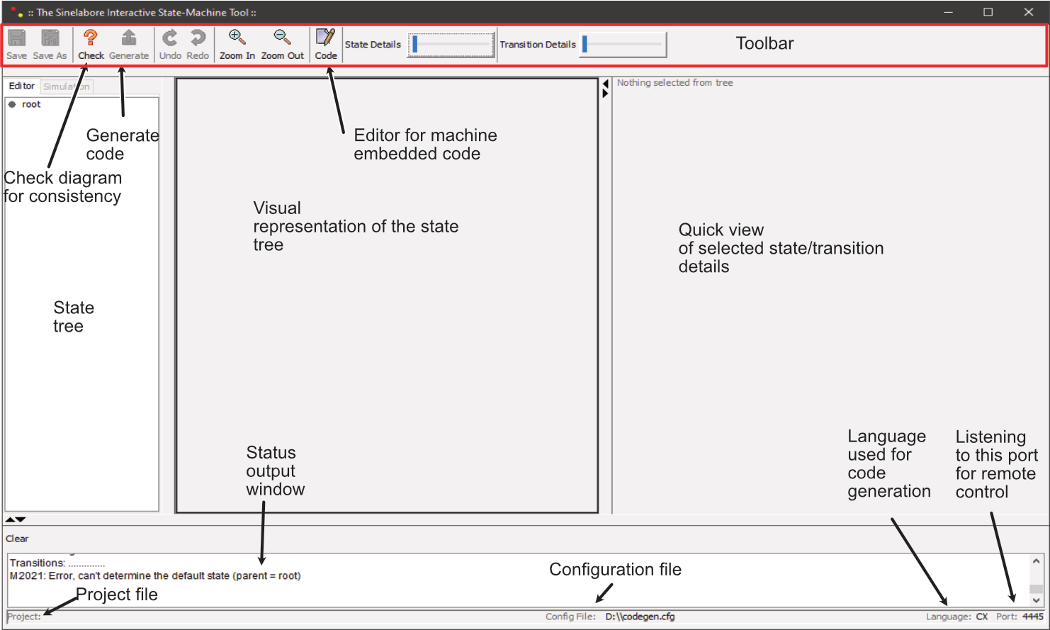
...State Machine Editor#
Overview#
The editor uses a tree-based approach instead of manual graphical layout. Diagram rendering is generated automatically, so no time is spent moving elements around. Dedicated fields support syntax highlighting and guard/action/entry/do/exit definitions.
Once a diagram is ready, code can be generated directly, or the model can be saved and processed by command line generation later (for example in a Makefile).
Starting the editor for the first time#
Open a command window (Windows) or terminal (Linux/macOS) and run:
c:\jdk-11\bin\javaw.exe -cp "c:/sinelaboreRT5.2/bin/*" codegen.Main -p ssc -E-E starts the state chart editor. -p ssc selects the native editor model format (XML-based and human-readable).
If no configuration exists yet, the editor asks for dot.exe. To avoid this in future runs, create codegen.cfg:
DotPathWin="c:\\Graphviz-2.44.1\\bin\\dot.exe"
# Use this on Linux/MacOS
# DotPath="/usr/local/bin/dot"
LicensePath=...
Store codegen.cfg in the user home directory so codegen can find dot automatically for future projects. If you have a license, add the license path there too.
After dot.exe is found, the editor opens with an empty workspace.
Creating a state diagram#
In this section we build the diagram shown in Figure 4.
Adding states#
Select the root node, right click, and choose Insert state. At minimum, specify a unique state name. Add entry and exit code as shown in the final example, then click OK.
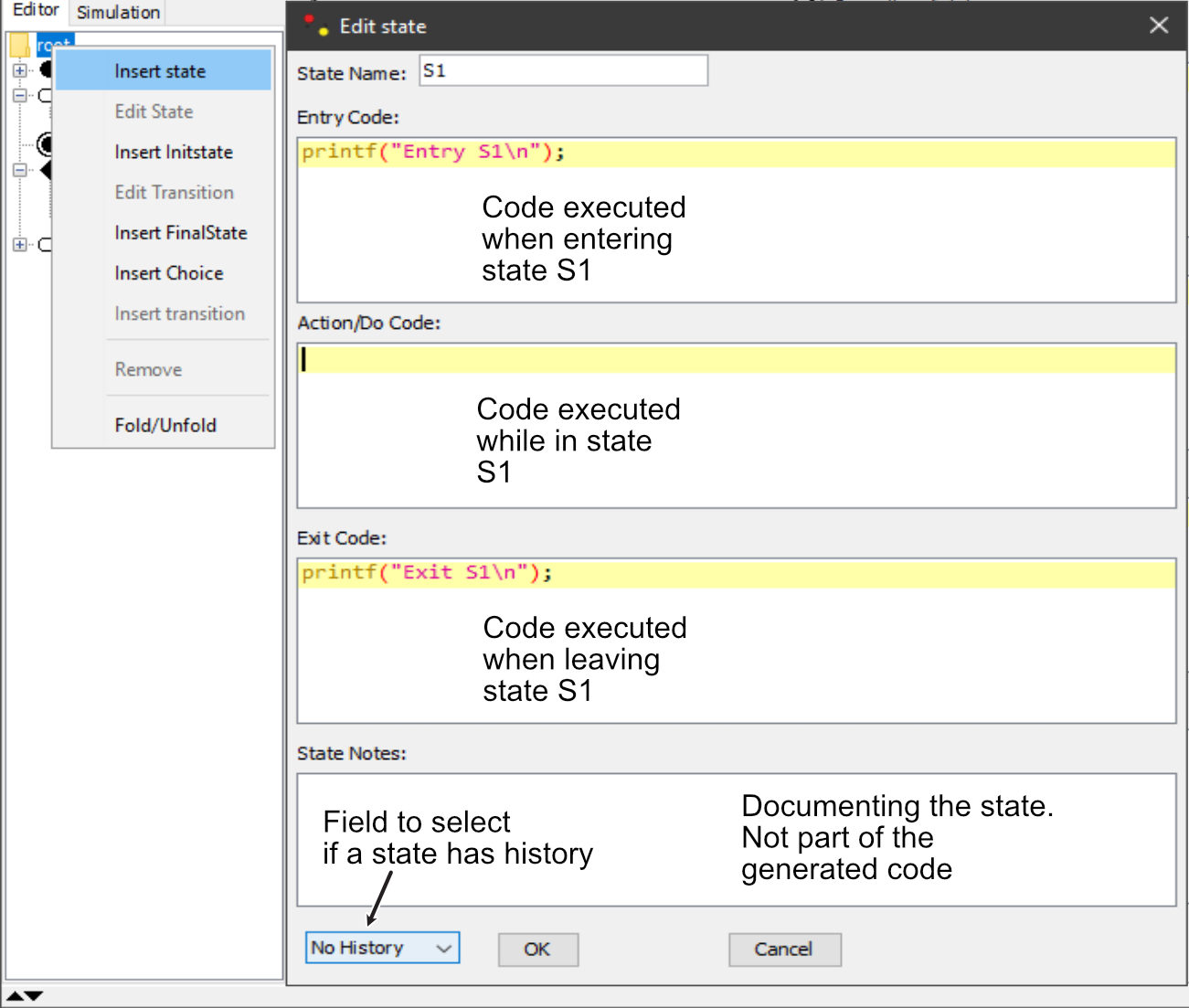
The first state appears and an init state is created automatically if needed. Add state S2 as shown in Figure 4.
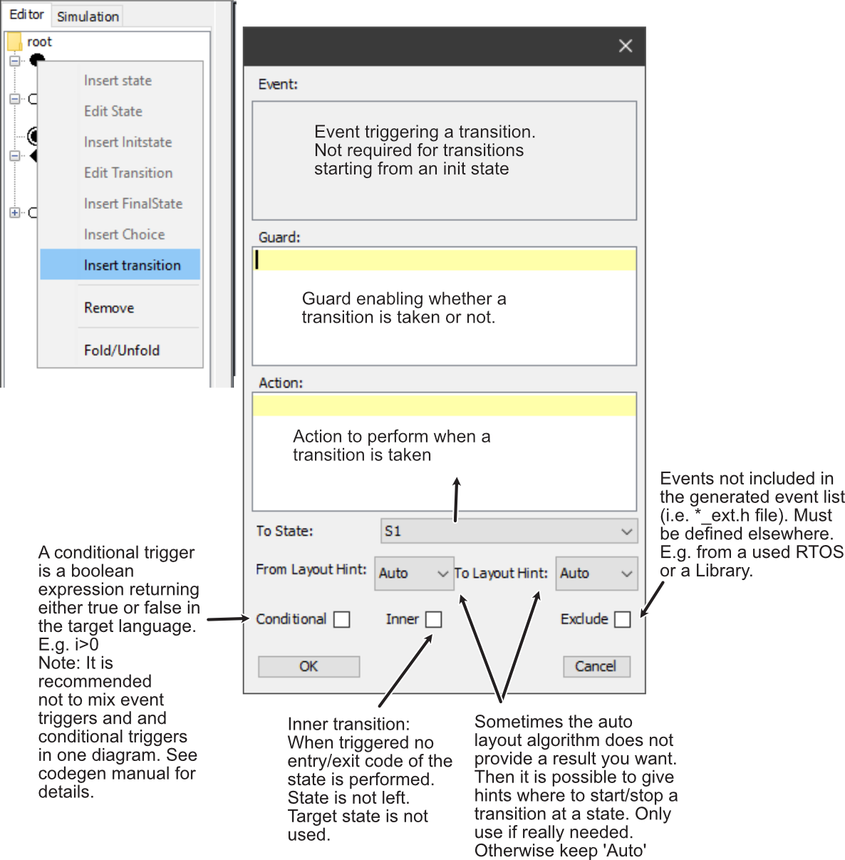
Adding transitions#
Right click a state in the state tree where the transition starts (for example the initial state), then choose Insert transition. Select a target state (here S1) and add event/guard/action as needed.
For an init-to-default transition, no triggering event is needed.
Adding a final state#
Add a final state from the root context menu. This is similar to adding a normal state, but without editable properties.
Adding a choice#
A choice represents dynamic branching. It must have one incoming transition and at least two outgoing transitions. Every outgoing transition needs a guard, and one guard should be else (default path).
Add a choice from the root context menu, then:
- add one transition entering the choice (with trigger)
- add two transitions leaving the choice (with guards)
- ensure one guard is
else
First diagram done#
After completion, the diagram should match Figure 4.
Use Save As and save as manual.xml.

To reopen directly with your project:
c:\jdk-11\bin\javaw.exe -cp "c:/sinelaboreRT5.0/bin/*" codegen.Main -p ssc -E manual.xmlGenerating code from your first state diagram#
Unlike many UML tools, the editor enforces valid diagrams (for example transition trigger presence and unique state names). If inconsistencies exist, the model checker warns and blocks save/generation until fixed.
Before generating code:
- Open the
Codewindow and configure target language and user code sections. - Define handler signature:
HsmFunctionWithInstanceParameters=yes
HsmFunctionWithEventParameter=yes- Add additional instance attributes via the
Attributesbutton if needed.
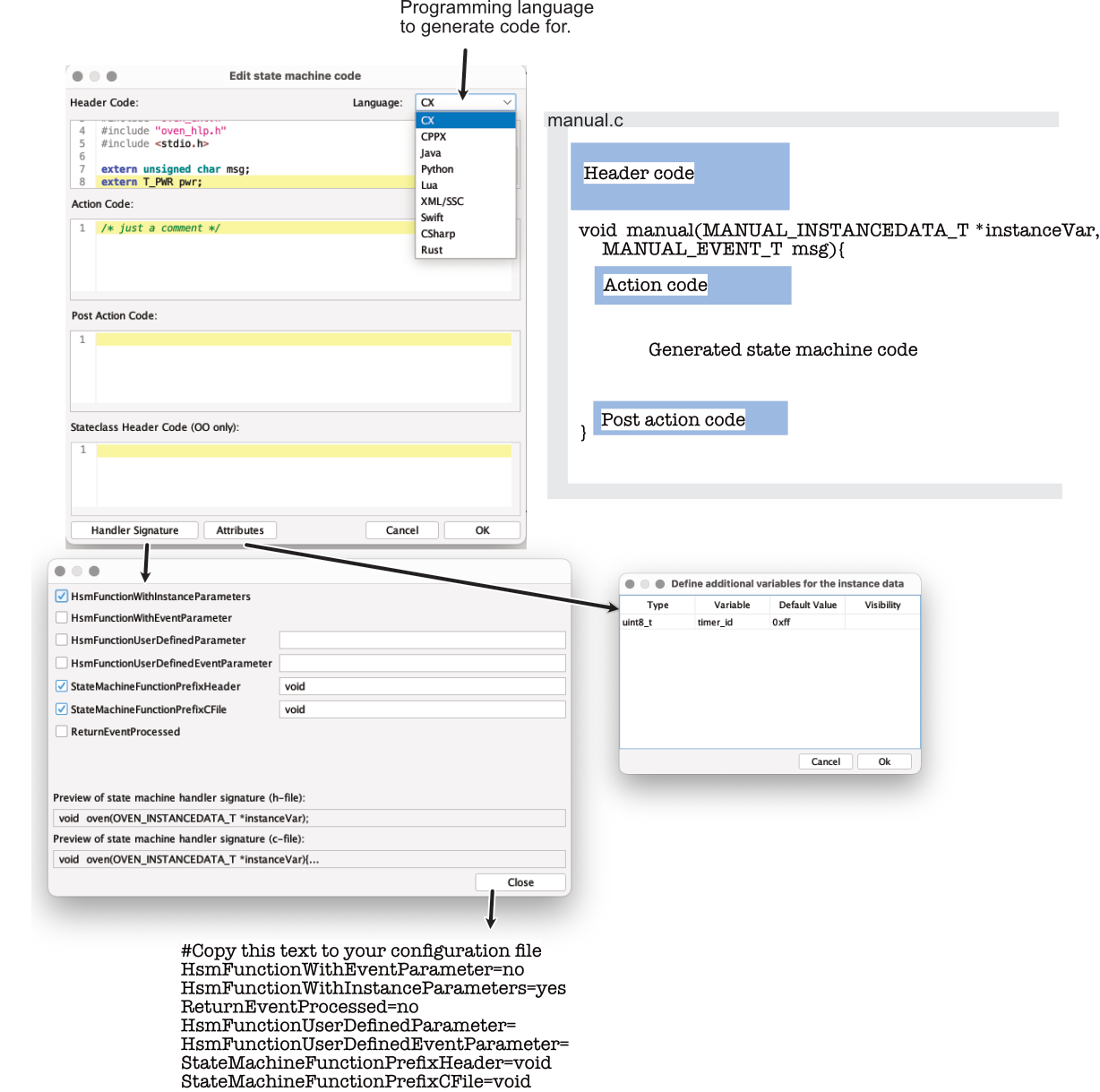
Code sections:
- Header code: includes, definitions, globals at top of generated implementation.
- Action code: executed at function start.
- Post action code: executed just before function return.
If validation is clean, press generate. Files are written next to the project file.
D:\>dir
 Verzeichnis von D:\

30.01.2021  17:37               137 codegen.cfg
30.01.2021  17:51             2.209 manual.c
30.01.2021  17:51               650 manual_ext.h
30.01.2021  17:51             2.232 manual.h
30.01.2021  17:51             1.990 manual_dbg.h
Generated files:
manual.cstate machine implementationmanual_ext.hmachine event definitionsmanual.hstate machine headermanual_dbg.hdebugging support
Compiling the first application#
Use a small main.c to stimulate the generated machine:
#include <stdio.h>
#include <stdint.h>
#include "manual_ext.h"
#include "manual.h"

MANUAL_INSTANCEDATA_T instData = MANUAL_INSTANCEDATA_INIT;

uint8_t i=0;

int main(void){
    manual(&instData, MANUAL_NO_MSG);
    printf("--\n");
    manual(&instData, ev1);
    printf("--\n");
    manual(&instData, ev2);

    printf("Now we set i>0\n");
    i=1;
    manual(&instData, ev2);

    // From now on no reaction is possible anymore because
    // the machine is in a final state
    manual(&instData, ev2);
    manual(&instData, ev1);

    return 0;
}
Compile:
D:\>g++ -Wall -pedantic main.c manual.c -o manual.exeRun:
D:\>manual.exe
Entry S1
--
Exit S1
ev1
Entry S2
--
Exit S2
ev2
Entry S2
Now we set i>0
Exit S2
ev2
i>0

D:\>
Wrapping up#
You learned how to install SinelaboreRT, model a first state machine, generate code, and run it.
As a next step, modify the diagram, regenerate code, and explore more options in the code generator configuration and command line parameters.
Have fun!
All details are described in the code generator manual (PDF).