State Diagram Editor Introduction Part III#
In the first part of the tutorial you learned how to create a first state diagram and to generate code from it. Then in the second part you learned the use of regions and what can be done with them.
In this third part of the tutorial you will learn how to simulate a created model to see for yourself if the machine does what it is supposed to do, or to walk through a model with colleagues or customers and confirm that the behavior is as expected.
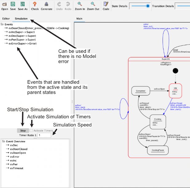
A model can only be simulated if it is error free. The absence of errors can be checked with the check button in the button bar. If there are no errors, simulation is possible in the Tree View.
Note: press pause where needed to better follow what’s going on.
Simulation without timer#
The simulation can be started with the Start button. Once simulation has been started, the events processed by the currently active state (in red) and its parents (also in red) are displayed. A click on an event triggers the state change. Afterwards, the possible events that originate from the new state are displayed. Events of a timer have to be triggered by a click just like all other events. A click on the Stop button ends the simulation.
The code “executed” in actions is recorded in the output window. This makes it possible to track which actions are executed when the state changes.
Note: actions refer to code entered as entry/exit/do code or transition actions.
Simulation with timer#
In state machines, one or more timers are often used to trigger time-controlled actions. Timers send a user-defined event to the machine at timeout. To simulate this semi-automatically, timer commands can be specified in action comments using a predefined notation. The timer commands are introduced by a special sequence, by default @@@, followed by timer commands in XML syntax.
To activate timer simulation, check the Activate Timers option before starting simulation. If timers fire faster than about 200 ms (depending on the computer), reduce Timer Ratio; otherwise the real-time image build-up is no longer possible and other events may no longer be clickable. By default, Timer Ratio is 1:1.
Link to a YouTube video showing timer simulation in action
The following functions are available. Times are always specified in ms. A unique timer ID is required. When creating a timer, the event must be specified (in the example evTimeout), which is injected into the simulator when the timeout expires. Timers can fire cyclically or once.
<TimerCreate timeout_ms="400" id="T1" event="evTimeout"/>
<TimerIncrement value_ms="100" id="T1"/>
<TimerDecrement value_ms="100" id="T1"/>
<TimerSetTimeout timeout_ms="400" id="T1" />
<TimerStartAcyclic id="T1" />
<TimerStartOnce id="T1"/>
<TimerStop id="T1" />
In the following video you can see how to work with simulation. After switching on the microwave oven, timer T1 is created. The user can then increase or decrease time via evDec/evInc. If the door is closed, timer T1 starts running. After time has elapsed, event evTimeout automatically switches to the completed state. In between, time can still be changed via evDec/evInc.
Note: it is important that entered program code for timers later realized in C or C++ matches the simulation code in comments. Since this is done in the same input field, this is usually straightforward.
Summary#
With simulation of your design you can easily understand behavior and check whether transitions or other elements were forgotten. Timer simulation further simplifies this and makes simulation more realistic.