State Diagram Editor Introduction Part II#
Overview#
In the first part of the tutorial you learned to create your first state diagrams and to generate code from them. In this part you get to know additional features of the graphical editor, especially handling regions.
In state diagrams usually only one state is active at a time. In UML state diagrams, regions allow modeling concurrency, meaning more than one state can be active at a time (AND states). A UML state may be divided into one or more regions. Each region contains its own state diagram. Regions are executed in parallel, so you can think of them as independent state machines displayed in one diagram.
Adding regions#
Let’s add regions to the diagram created in Part I. Right click on state S1 and add a region. Then add another region. A default name is defined, but you can change it during creation or later at any time. Add a state to each region with entry and exit code, then create transitions from each init state to those new states.
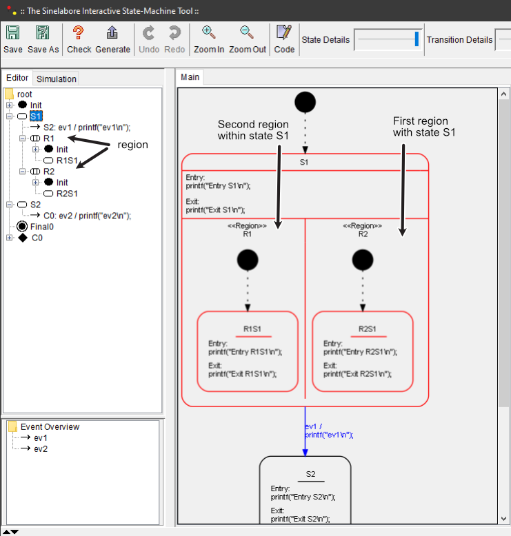
You may have noticed that transition targets are limited to states within the same region. That is expected: transitions cannot cross regional boundaries.
If a state contains only one region it is basically equivalent to a hierarchical state. Still, using a single region can be useful to visualize states in a separate diagram.
To convert hierarchical states into a region, use the context menu action Convert State into new Region. This creates a new region and moves existing children into it.
The opposite is also possible: choose Convert to State with Children.
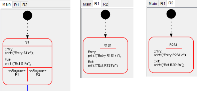
Regions can be displayed in a single large diagram or in separate diagrams. To display a region in a separate diagram, right click on the region and choose Display Region in separate Tab. A new tab with the region diagram is shown, which is useful when more space is needed.
As before, check your design, save it, and generate code.
Compile and execute again. The output looks like this:
D:\>manual
Entry S1
Entry R1S1
Entry R2S1
--
Exit R1S1
Exit R2S1
Exit S1
ev1
Entry S2
--
Exit S2
ev2
Entry S2
Now we set i>0
Exit S2
ev2
i>0

D:\>
As you can see, the entry and exit code of both regions inside S1 is executed when entering or leaving S1, so they run “in parallel” while the machine is in S1.
Exporting parts of your diagram#
If you want to export parts of your diagram for reuse in another diagram, right click the state to export and select the export command. The exported diagram is copied as XML to the clipboard. It can be imported immediately into another diagram or saved in a text file for later reuse. This helps build a library of reusable state machine diagrams.
Wrapping up#
Regions are a powerful mechanism to model machines that are in more than one state at the same time. For example, a microwave oven can simultaneously “turn the motor”, keep “the light on”, and enforce that “the door must be closed”.
The examples folder contains the microwave model both as a hierarchical UML model and as a region-based model.