Master State Machines for Real-World Firmware#
On this page you will learn what state diagrams are, what they consist of, and how to create them. Different modeling tools are used throughout this introduction to show that the code generator is tool-independent.
A state machine shows the dynamic behavior of an application. It is a graph of states and transitions that describe the response to events depending on the current state. State machines have been used for decades in hardware design, and in recent years increasingly in software development. UML state machines have some significant improvements compared to classical Moore or Mealy state machines. They support hierarchical designs, it is possible to model parallel execution (and states) and several pseudo states were added to further improve expressiveness.
Especially in the embedded real-time domain the use of state machines is popular because the behavior of devices in this domain can be often very well described with state machines.
An important aspect of state machines is that the design can be directly transformed into executable code. This means that there is no break between the design and the implementation. This is all the more important if the device under development has to be certified (for example according to IEC61508).
The following picture shows a hierarchical state machine that is used throughout this introduction.
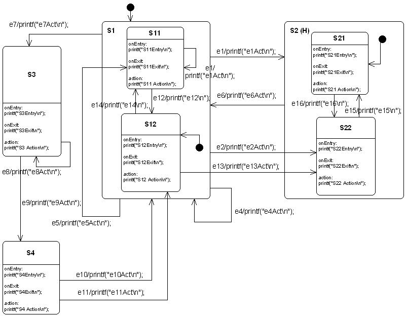
Figure: This state diagram example shows many of the features supported by the code generator. It was created using the Cadifra UML editor.
State Machines are Trees#
Basically a state machine can be represented as a tree of states. A transition e13 connects the two states S12 and S22. If the transition is triggered you have to walk upwards in the tree starting from S12 until you reach a common parent of S12 and S22. Then walk downwards in the tree until the target state (in this case S22) is reached. On the way all the entry and exit code of the visited states has to be executed.
If the starting state is a composite state, it must also be determined which child state to exit. If the target state is a composite state, it must also be determined which child state to enter. If history states are used, their history must be considered when entering states.
Luckily the code generator takes care of all these conditions in the generated code. So you don’t have to worry about all the details involved in implementing state machines in a specific language.
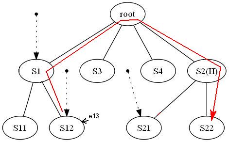
Figure: The code generator internally creates a tree from a state diagram. Here the state tree of the example state machine is shown.
States#
State machines can be hierarchical or flat. A machine with sub-states within states is called a hierarchical state machine. States can have entry code that is always executed if a state is entered. Exit code is executed whenever the state is left. Note that entry and exit code is also executed for a self-transition (for example e4 or e8 in the example machine). If events should be processed without triggering entry and exit actions, so-called inner events can be used. If a state has no entry and exit actions, an inner event behaves like a self-transition.
A state can also have a do activity. Do activity code is executed whenever the state is active, just before event transitions are evaluated. This means calculation results from action code can be used as transition triggers. Every state must have a unique state name.
Actions (entry/do/exit code) within states should be non-blocking and short regarding execution time. On every hierarchy level, a default state must be specified. A final state is a state that cannot be left anymore, so the machine must be re-initialized to be reactive again.
Some UML tools make it difficult to define action code (for example a few C statements). Therefore, it is possible to specify inner events, entry code, and exit code for a state by linking a note to the state. The note must start with compartment:. Sometimes this is useful even when the UML tool supports direct entry/action/exit fields. Since constraints: is not supported by many UML tools, it should be defined in an attached comment note (see section 3.6 in the PDF manual).
In principle states can be nested again and again. The code generator was intensively tested with up to four hierarchy levels. If you use more levels reconsider your design!
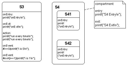
Figure: Left: A state with entry-, exit-, action code and inner events. Right: Complex state with entry- and exit code specified in a linked note.
Transitions#
There are two types of transitions supported by the code generator: a) event-based transitions and b) condition-triggered transitions. An event-based transition has the following syntax: eventName[guardExpression]/action. The transition is only taken if the guard expression evaluates to true and the event was sent to the state machine. Only in this case is the action code executed.
From a transition like
the code generator generates the following C code:
if((msg==(OVEN_EVENT_T)evDoorClosed) && (timer_preset()>0)){
  /*Transition from Idle to Cooking*/
  evConsumed = 1U;
  /*Action code for transition */
  timer_start();
  ...
}
A conditional (guard) transition is not triggered by an external event but when a guard expression evaluates to true. The hash character # must prefix the condition to indicate this trigger type.
It has the syntax:
the code generator generates:
if((i==1)){
   ...
   /*Action code for transition*/
   printf("i==1\n");
   ...
}
Externally defined events: usually for all events used in a state machine diagram, event definitions are generated in *_ext.h, and only those events can be handled by the state machine.
But sometimes it is required to react on events defined externally from the state machine diagram (e.g. existing code is re-used defining own events or the operating system sends predefined events e.g. in case of a timer timeout).
The code generator needs to know whether an event should be included in event definition generation. Such events can be prefixed with !. In all other generation stages (state machine handler, debug helpers, etc.), they are handled like any other event.
Action code defined in transitions must be non-blocking! The next figure shows examples for all types of supported transitions. Action code from an initial pseudo state is only used if the target state of the transition is not in a parent state with history. In history states the usage of actions on the init transition is often misapplied and therefore ignored!

Examples of possible transitions supported by the code generator.
From top to bottom:
- Transition from an init pseudostate (only action expression allowed)
ev1: Simple event with no guard and no action- Event with guard
[]expression) - Event with guard and action
- Conditional transition (
#i == 0) - Conditional transition with action
- Transition defined externally e.g. in a library
Choices#
The OMG UML specification states that choice vertices realize dynamic branching by evaluating guards on outgoing transitions.
The state chart in the next figure shows different options for how choices can be used. Choices are represented as diamonds. They can be placed within a composite state or at root level. A choice must have at least one incoming transition. Guards specified on incoming transition(s) are ignored by the code generator. Actions are simply copied to the outgoing transitions, so place them there.
Usually, choices have one incoming transition and multiple outgoing transitions (at least two). However, the code generator also allows more than one incoming transition. This is a convenient feature for compact specification of complex structures. Internally, this construct is handled like two choices with one incoming transition each and the same outgoing transitions.
If more than one incoming transition is found, the choice is duplicated for each incoming transition. In other words, it is like modeling two choices with one incoming transition each and the same outgoing transitions. At least two outgoing transitions must be defined, each with a guard. One of the guards must be an else statement as described above. Depending on the target state of each outgoing transition, the related entry/exit code is generated. Creating chains of choices is not supported.
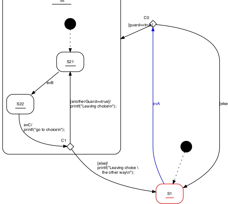
▲ Different options to use choices. A default path marked with
else must always exist.
Determining the default state dynamically (Init to Choice)#
Sometimes the initial state of a state machine or sub-machine must be determined at runtime rather than at design time. Examples:
- If hardware self-test fails, enter an error state instead of normal operation
- Enter a specific state based on a parameter set at runtime
In such cases it is possible to connect the initial pseudo–state with the input side of a choice and connect the outgoing transitions with the target states. It is important that there exists one else path to ensure that there is always one option that can be taken by default. Several examples are shown in the following figure. Note that it is possible to define an action on the incoming transition of a choice that reads a value or performs a check and use the result of that function as guard for the outgoing transitions of a choice.
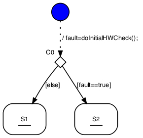
▲ Choices can be used to determine the initial state at runtime. The figure shows several possibilities how to use this feature.
Junctions#
The OMG UML specification defines junctions as semantic-free vertices used to chain multiple transitions and construct compound transition paths.
The UML specification also discusses the possibility of multiple outgoing transitions. This is not supported by the code generator!
Junctions can be seen as a drawing helper when several transitions all end in the same state and share a common action. In such a case, place the different triggers, guards, and action code on the incoming transitions, and place the common part on the outgoing transition.
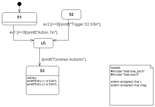
▲ Junction example drawn with Cadifra UML. There is no junction symbol available in Cadifra UML. The shown (J) state is the supported replacement.
The code generator creates two separate transitions from this model: one from S1 to S3 and one from S2 to S3.
Limitations and rules:
- A junction should have at least two incoming transitions
- A junction must have exactly one outgoing transition
- On the outgoing transition, no guard and trigger must be defined
- Outgoing transition action is appended to incoming transition actions
- Incoming transitions must not start from pseudo states (junction, choice, …)
- Outgoing transition must not end in pseudo states (junction, choice, …)
Final States#
Final states have only incoming transitions. Once a state machine enters a final state it will not react on any other event. Exceptions are final states inside a hierarchical state machine. Transitions leaving the parent state of a final state can still be taken. In the next figure, the state Final can be left via ev3 or evRealEnd while state Final1 cannot be left anymore.
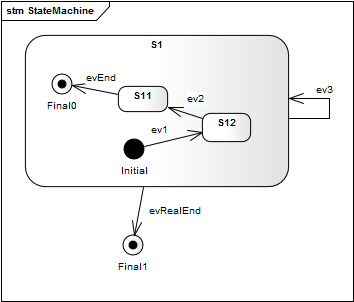
▲ Example usage of final states. Once the machine is in state Final1 it cannot be left anymore. State Final can still be left via event.
Regions#
In state diagrams usually only one state is active at a time. In UML state diagrams regions also allow to model concurrency – i.e. more than one state is active at a time (AND states).
A UML state may be divided into regions. Each region contains substates. Regions are executed in parallel. You can think of regions as independent state machines displayed in one diagram. The state machine in the next figure shows the well-known microwave oven example designed using regions, with several regions running in parallel in state Active. Dashed lines are used to divide a state into regions.
The power setting, light, and microwave radiator are considered independent (concurrent) parts of the oven, each with its own states. The door and timer are the main external triggers used in the regions to trigger state transitions. For example, the radiator is switched on if the door is closed and the timer is > zero.
As you can see, multiple concurrent regions can be used to explicitly visualize different parts of a device and all states in one diagram.
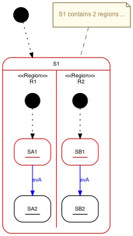
▲ State S1 contains two regions.
Points to consider with regions
- Transitions must not cross region boundaries
- Regions must work on consistent instance data (run-to-completion semantics)
Adapting the Generated Code#
To adapt the generated code to your needs, you can add notes to your design that start with either header:, postAction:, action:, or unknownStateHandler:.
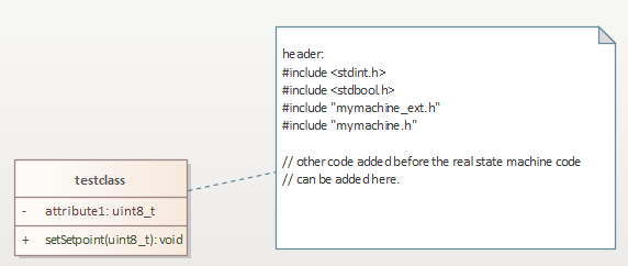
▲ It is possible to define own code inserted on top of the generated file. This allows to specify own include files or other required local code in the state machine file.
- Code after
header:is added at the top of generated machine code - Code after
action:is inserted at the beginning of the state handler function - Code after
postAction:is inserted at the end of the state handler function - Code after
unknownStateHandler:is inserted in generated default branches
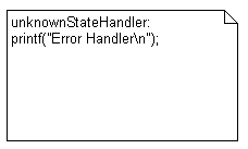
▲ A message is printed whenever an invalid state variable was found.