Using Statemachines with the embOS Real-Time Operating System (RTOS)
This article shows how to use state charts in the context of a real-time operating system. In this example the WIN32 version of embOS from Segger is used as an RTOS. So you can build, modify and run the example yourself!
The Starting Point
System partitioning often requires to run state machines in different tasks, timer handlers or interrupt service routines. The different state machines then typically communicate through interprocess communication mechanisms provided from the operating system such as queues or messages (aka active objects). The following figure shows a fictive system with different active parts and their relation.
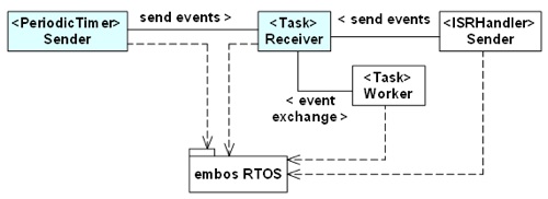
In this example the two blue marked parts (a task and a timer) are modelled as state machines. The Sender periodically sends different events to the Receiver. The receiver task then reacts on the received events. The two state machines are kept simple and just print out some trace messages. But this is enough to understand the design principle.
Implementation
Step 1: Modelling the sender & receiver state machines
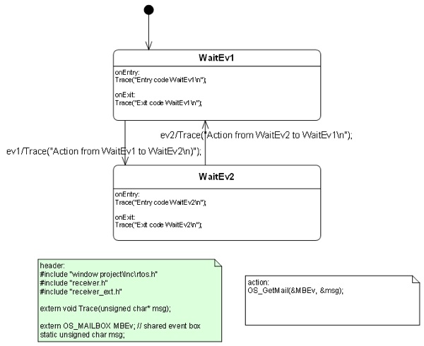
For each state machine an own UML state diagram has to be developed. The diagram for the Receiver is shown first. The two accepted events are ‘ev1’ and ‘ev2’. Whenever an event is received a state change happens. The code provided after the ‘action‘ keyword (right note) is inserted from the code generator at the beginning of the state machine handler. This code reads the next available event from a mailbox, otherwise it blocks. The code following the ‘header‘ keyword (left note) is inserted at the beginning of the generated code. It includes the required header files and declares the needed variables (e.g. the shared mailbox).
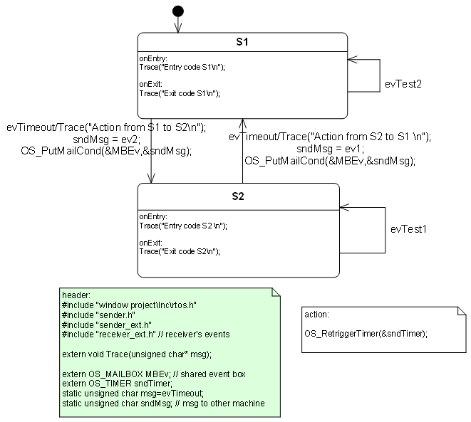
The next diagram shows the sender machine. Whenever the timer fires a state change happens (evTimeout). The action code in the transitions put new messages in the message box. The timer is re-triggered (→ see action code) after each timeout.
Step 2: Integrate the state machines
In our example the sender state machine is called from within the embOS timer callback function.
// embOS timeout callback function
void TimerHandler(void) {
   sender(&sndInst);
}
The receiver state machine is called from the task body.
// receiver task
void Task0(void) {
   while(1){
       OS_Delay(50);
       receiver(&recInst);  // state machine function blocks if no event is available
   }
}
Nothing else is required. The generated code does not need any other runtime libraries!
Conclusions
As you can see it is quite simple to use generated state machine code in the context of an real-time operating system. It is also possible to run a state machine function from within an interrupt service handler. Checkout the manual on how to set the related generator flags.
To change the state diagram you need the Cadifra UML editor which was used to design the example. Demo versions of Cadifra and the Sinelabore code-generator are available in the download area. To compile the code you also need the Visual C++ Express Edition from Microsoft. The source code and the executable is provided for download below. After starting the exe the trace output is written to c:\trace.txt. No other output is shown on the screen!
Download the embos example here.