Table of Contents
Building a ModbusRTU server with state machines, activity diagrams and minimal runtime environment
In one of the last design articles I described how to use state-machines in low power embedded software design together with timers and queues to create a wireless sensor node.
This time I use the same architecture to design and implement a basic ModbusRTU server. A UML state machine diagram shows the core behavior of the server. An activity diagram shows how the received frame is checked and a reply telegram generated. The server supports not all function codes and has a simple address map. But it will be easy to expand the design with more features.
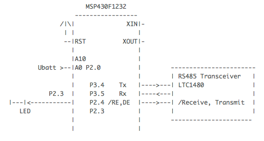
The design is based again on a small TI MSP430 board already used in the previous article. The whole server runs in less than 256 bytes of ram and needs only few kilobytes of code. A RS485 interface was added as physical interface as defined by the ModbusRTU specification.
Modbus defines function codes to read/write either bit or word data. Function code four is defined to read analog input words (in our case only simulated values). Function codes one and five are defined to read/write digital outputs (coils). For demo purposes a LED is connected to a port pin of the µC.
For those not familiar with Modbus and ModbusRTU. Have a look www.modbus.org and search for the technical specification of the RS485 layer and the ModbusRTU server protocol.
Overall System Design
The model was realized with the Astah UML Editor. The model file is available here modbus.asta for download. The fastest overview provides an interaction diagram (see below). The relevant players are:
modbus: The central function realizing the modbus server functionality. The code was fully generated from a state machine diagram discussed later on.modbus_helper: Helper functions used from the state machine and the rx frame checking code.ringbuf,timer,crc16…: Library classes that can be reused from project to project. These classes were already used in the previous examples (e.g. wireless temperature sensor).timerA: Hardware timer to generate system tickrs485: serial interface handler
The main() function initializing the hardware and software is not shown. It cyclically calls the modbus state machine and timer. In case of any pending events the modbus state machine is called.
For practical reasons classes were implemened as C/H files and member functions as C-functions. In the case a class is used multiple times instance data is packed into a structure and provided as reference to the functions. An example for this “object aware programming” is the fifo class.

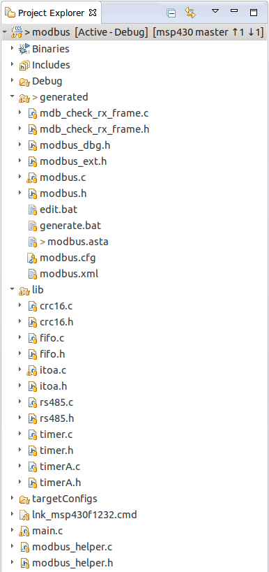
Beside the object interaction diagram the following workspace view shows the project structure and used/generated files.
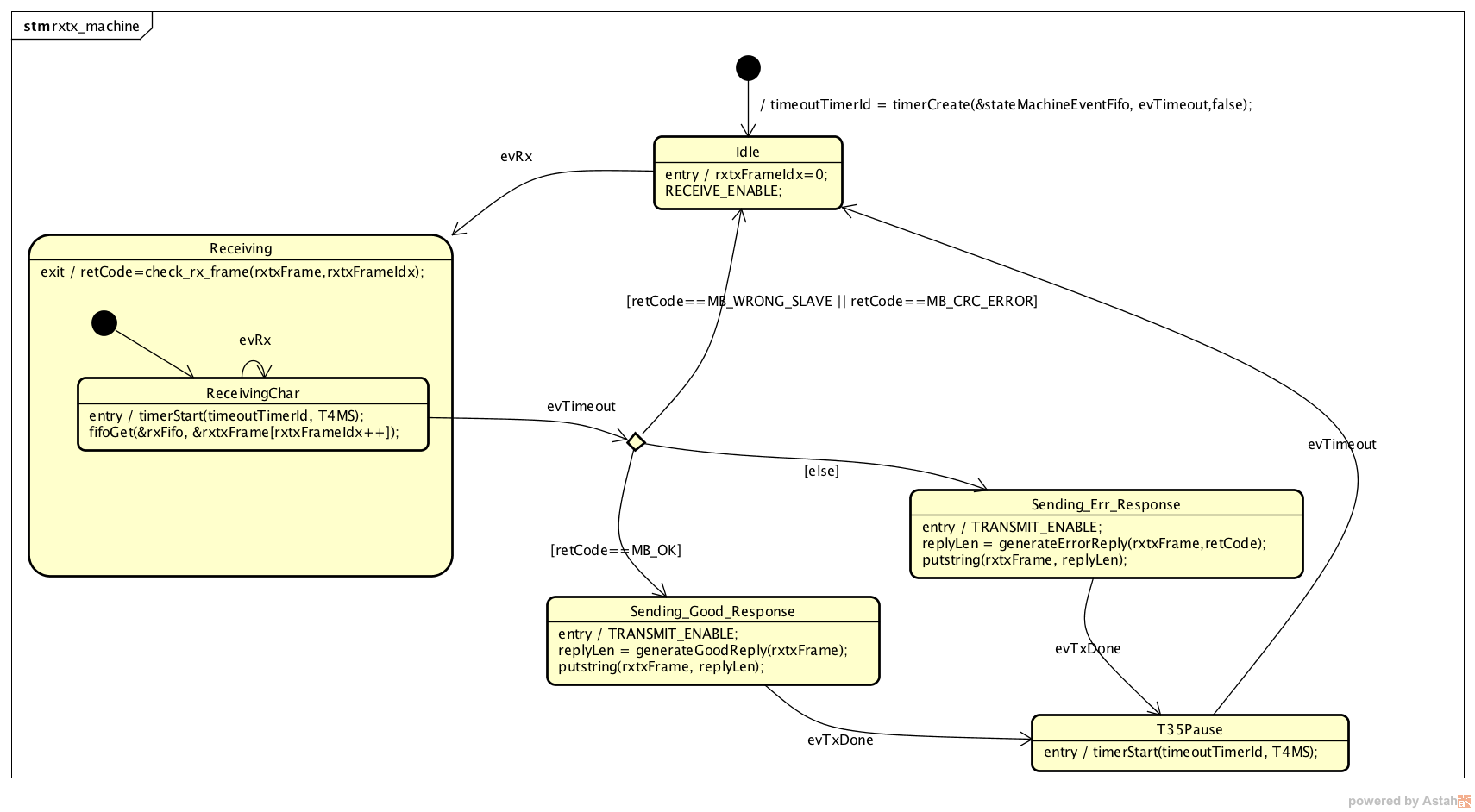
ModbusRTU State Machine
The state machine starts in state Idle. It initially enables the receiver and waits for the first byte. Then it changes to state Receiving until the complete frame was received. Every new byte retriggers the timer. The condition to detect that a complete frame was received is not receiving any new byte for a given amount of time (depends on baud rate, about 4ms @ 9600 Baud). The timer event evTimeout indicates this. The frame is checked before exiting the Receiving state (explained later on). Depending of the check result the machine either
- enters
Idleagain without answering the request (see Modbus spec) - enables the transmitter and sends an error message back to the master
- enables the transmitter and sends requested information back to the master.
When the complete reply frame was sent - indicated by event evTxDone from the rs485 transceiver - the state machine waits for about 4ms to indicate frame end and then goes to state Idle again waiting for the next frame.
Despite the ModbusRTU state machine looks simple it implements everything required for a slave!
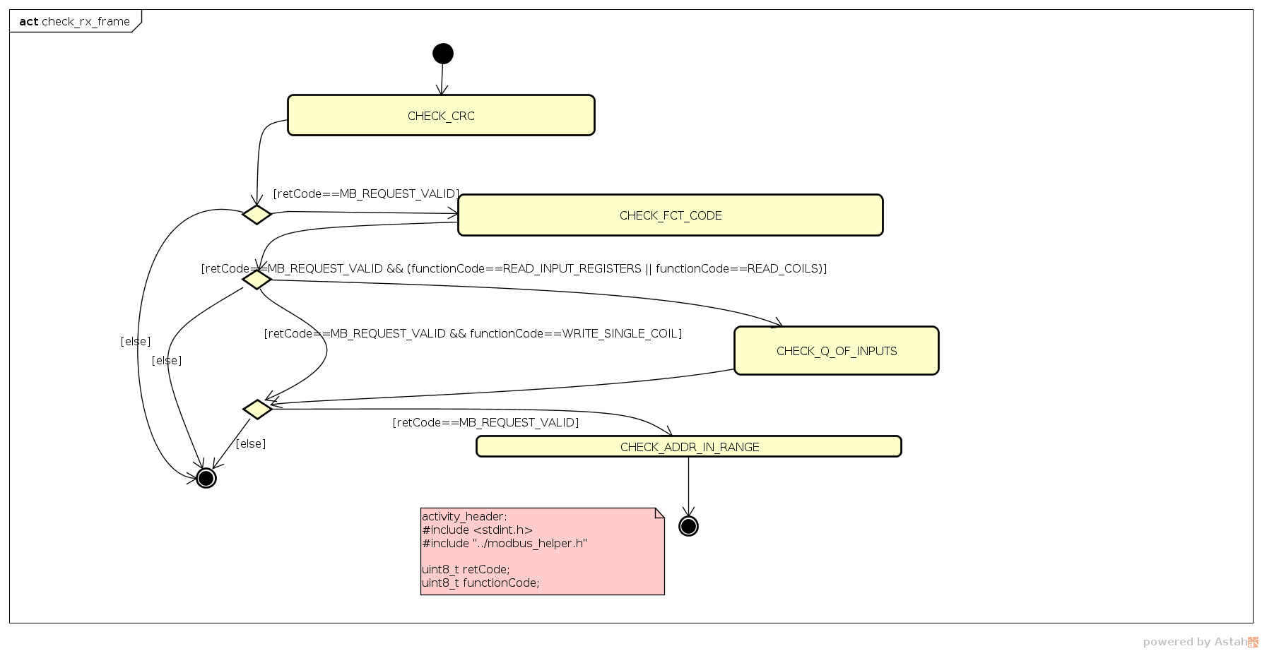
Checking the Received Frame
Quite some complexity is hidden in checking the received frame (exit code of state Receiving). Therefore this function is designed with the help of an activity diagram and is fully generated from the code generator. The ModbusRTU specification uses flow charts. I tooke over the flow charts to a certain extend and reused that way what the ModbusRTU designers put into the spec.
The ModbusRTU spec contains an own flow chart for each function code. The presented design combined these single diagrams into just one activity diagram. As a consequence the single activities (e.g. check number of inputs, check valid address range) uses the function code to distinguish different requests. It is a matter of taste if this should also be made explicit in the activity diagram.
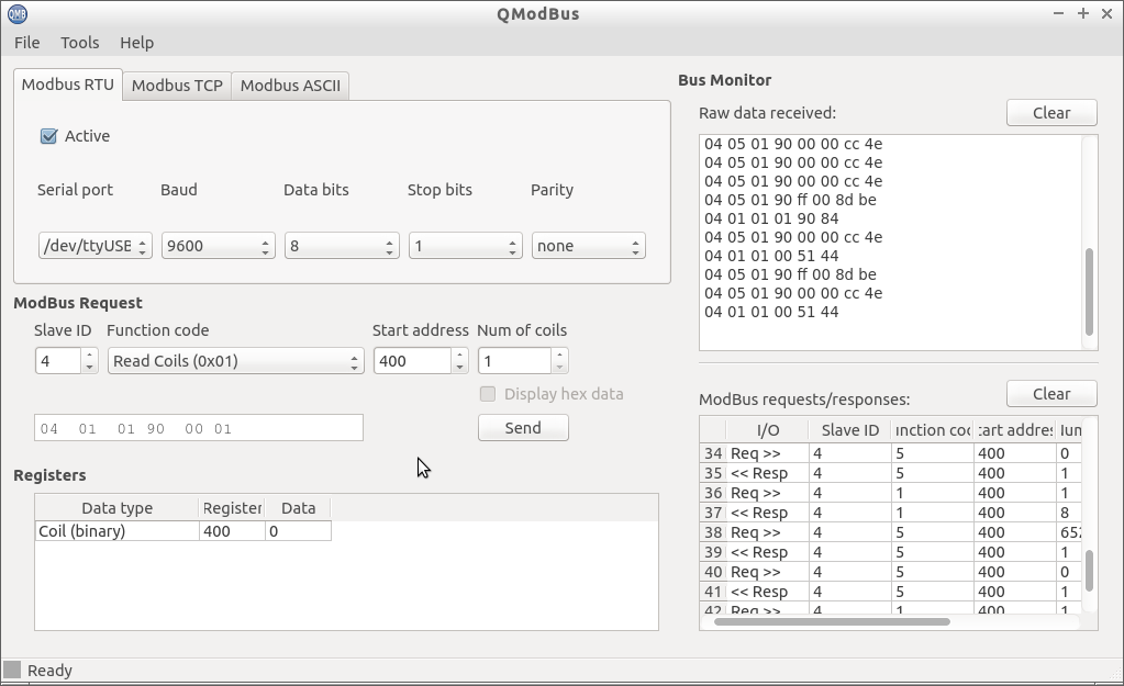
Testing
To test the complete design and implementation a ModbusRTU master is required. The next figures shows QModbus [2] running on a Linux box. There are also other command line tools which makes batch testing simpler.
The timing of the final device is shown below. D0 shows the system clock generated by hardware timer A. It calls the timer tick function. If no timer events were detected the CPU enters low power mode again. D2 shows the receiving telegram. D1 the transmission telegram. The CPU replys within 14ms. This could be further optimized if needed. The RS485 line is shown in the bottom part as differential signal (CH1-CH2).

One hint regarding stack-check: During development I had the need to check how much stack my code needs. I found the following code snipped on the web which turned out to be very useful. After running my test cases I could directly see how much space was left just looking at the memory browser window.
    // for checking the stack later on
    extern unsigned int _stack;
    extern unsigned int __STACK_END;
    unsigned int* p;


    p = &_stack;
    while (p < (&__STACK_END -3))
    {
        *p = 0xA5A5;
        p++;
    }
    // end for checking the stack later on
Wrapping Up
This article has presented the design of a MobusRTU server. It is is based on some library classes which can be reused from project to project. In addition state machine and activity diagrams were used to model the behavior of the device. From these models code was generated. So the design and the code will be always in sync and the modes are not just drawings!
The source code and model file is available upon request. I'm happy to receive suggestions for improvement which I will add and make available for others again.
Hope you enjoyed this article. Let me know your feedback! Peter
~~DISCUSSION:closed|Leave your comments~~
References: [1] www.modbus.org [2] http://qmodbus.sourceforge.net