This is an old revision of the document!
Table of Contents
Room Thermostat
This example shows the model of a room thermostat that controls heating, cooling and a fan to maintain a user defined temperature.
It uses regions to model the three parts of such a controller.
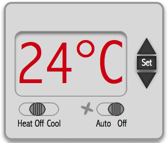
- The user interface that allows to set the temperature for heating or cooling using the set, up and down key.
- The temperature controller that tries to maintain the user selected temperature
- The fan that is active in case furnace or air condition is on.
The thermostat model is based on an example from Testcover.com.
Why regions are useful
In state diagrams usually only one state is active at a time. In UML state diagrams regions also allow to model concurrency - i.e. more than one state is active at a time (AND states).
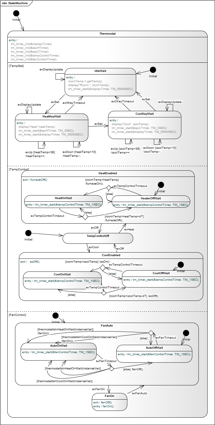
A UML state may be divided into regions. Each region contains sub-states. Regions are executed in parallel. You can think of regions as independent state machines displayed in one diagram. The state machine below (Fig. 1) shows three regions each running in parallel. Dashed lines are used to divide a state into regions.
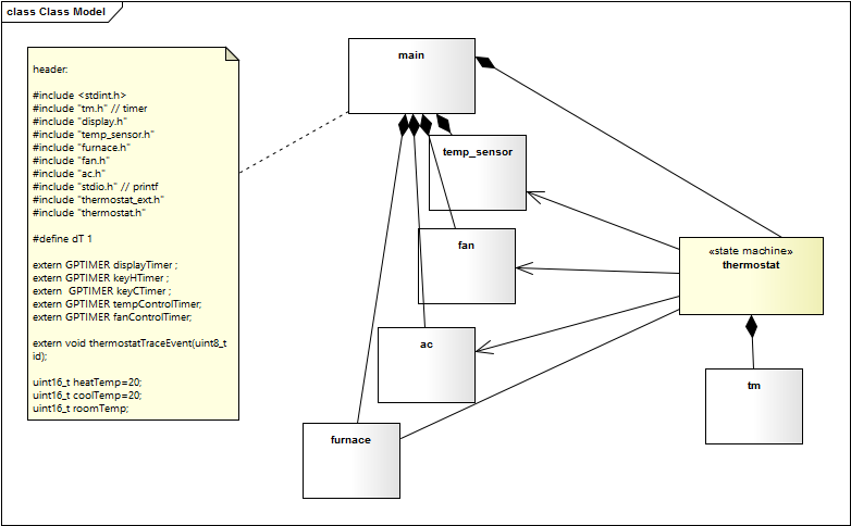
 Class diagram. In the attached comment C-code can be defined that is just included into the generated state machine code.
Regions are useful in the following situations
- Regions react on the same set of events. Implementing all the functions in one state machine does not require to model two machines with the same set of events.
- Regions need access to the same internal variables or helper functions. In the thermostat case the first two regions need access to the user settings such as
coolTemp,heatTempand the current room temperature (roomTemp). - Regions need to know the state of other regions. In the thermostat example the
fan controlregion changes state based on the state of theheat controlregion.
In fact it would be possible to model the three regions as individual machines, but due to their close interaction is makes sense to model them in one state diagram.
Implementation
The following state diagram in figure 2 shows the classes (i.e. C-files) involved in the solution. The thermostat is the central state machine. It is fully generated from the state machine diagram shown in figure one. For code generation only the yellow marked information is needed. All other classes are more or less documentation.
The helper classes are just examples and simply print out the name of the called action on the console. Here is an example for the fan implementation:
#include <stdint.h>
#include <stdio.h>
#include "fan.h"

void fanOff(){
    printf("Fan Off\n");
}


void fanOn(){
    printf("Fan On\n");
}
The timer implementation is taken from a recent article published on Embedded.com.
In main.c the keyboard is cyclically scanned and the user can send events to the machine (e.g. increment the room temperature).
The following code shows an extract of the generated state machine code. In case you are interested in the full example running on various operating systems just send a request to info@sinelabore.com.
void  thermostat(THERMOSTAT_INSTANCEDATA_T *instanceVar, THERMOSTAT_EVENT_T msg){

	THERMOSTAT_EV_CONSUMED_FLAG_T evConsumed = 0U;

	/* Create a copy of the instance data.
	   Changes during the machine execution are done on the copy
	   while tests (e.g. isIn) must use the unmodified instance data */
	THERMOSTAT_INSTANCEDATA_T instanceVarCopy = *instanceVar;

	/*execute entry code of default state once to init machine */
	if((&instanceVarCopy)->thermostatEntry==1U){
		tm_timer_init(&displayTimer);
		tm_timer_init(&keyHTimer);
		tm_timer_init(&keyCTimer);
		tm_timer_init(&tempControlTimer);
		tm_timer_init(&fanControlTimer);

		tm_timer_start(&fanControlTimer, TM_1SEC);
		roomTemp = getTemp();
		display("Room:", roomTemp);
		tm_timer_start(&displayTimer, TM_500MSEC);


		(&instanceVarCopy)->thermostatEntry=0U;
	}


	switch (instanceVar->stateVar) {

		case Thermostat:
			/* calling region code */
			evConsumed |= thermostatThermostatFanControl(instanceVar, &instanceVarCopy, msg);
			evConsumed |= thermostatThermostatTempControl(instanceVar, &instanceVarCopy, msg);
			evConsumed |= thermostatThermostatTempSet(instanceVar, &instanceVarCopy, msg);
		break; /* end of case Thermostat  */

		default:
			/* Intentionally left blank */
		break;
	} /* end switch stateVar_root */

	/* Save the modified instance data */
	*instanceVar = instanceVarCopy;
}
In this example we have shows how regions can be beneficially used for modeling parallel actions and how easy it is to generate code from the state diagram. The generated code can be adjusted to your needs and requires no additional run-time libraries.