This is an old revision of the document!
Table of Contents
New beta version supporting regions
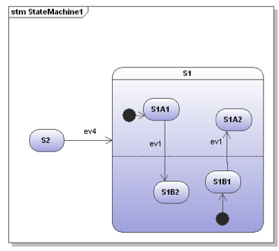
In state diagrams usually only one state is active at a time. In UML state diagrams regions also allow to model concurrency - i.e. more than one state is active at a time (AND states).
The latest beta now supports the modeling of parallel regions with the following constraints:
- Transitions must not cross region boarders. Why this is important is discussed further down
- No regions in regions
- No support for fork
- Join can be realized with transitions using guards like
isInS221 && isInS222as an example - UModel and EnterpriseArchitect as modeling tools
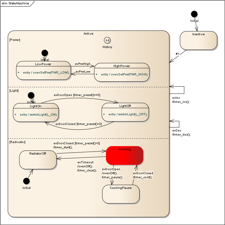
Here is the simplified C-code example of the oven state machine.
void  oven(OVEN_INSTANCEDATA_T *instanceVar){

  OVEN_EV_CONSUMED_FLAG_T evConsumed = 0U;
  OVEN_INSTANCEDATA_T instanceVarCopy = *instanceVar;

  switch (instanceVar->stateVar) {

    case Active:
      /* calling region code */
      evConsumed |= ovenActiveLight(instanceVar, &instanceVarCopy, msg);
      evConsumed |= ovenActivePower(instanceVar, &instanceVarCopy, msg);
      evConsumed |= ovenActiveRadioator(instanceVar, &instanceVarCopy, msg);

      /* Check if event was already processed  */
      if(evConsumed==0U){
        .... /* handle event on parent level */


    break;
   } /* end switch stateVar_root */

   /* Save the modified instance data */
   *instanceVar = instanceVarCopy;
}

OVEN_EV_CONSUMED_FLAG_T ovenActiveLight(OVEN_INSTANCEDATA_T *instanceVar, OVEN_INSTANCEDATA_T *instanceVarCopy, OVEN_EVENT_T msg){
  ...
}

OVEN_EV_CONSUMED_FLAG_T ovenActivePower(OVEN_INSTANCEDATA_T *instanceVar, OVEN_INSTANCEDATA_T *instanceVarCopy, OVEN_EVENT_T msg){
  ...
}

OVEN_EV_CONSUMED_FLAG_T ovenActiveRadioator(OVEN_INSTANCEDATA_T *instanceVar, OVEN_INSTANCEDATA_T *instanceVarCopy, OVEN_EVENT_T msg){
  ...
}
And the same example for C++:
// State machine event handler
int oven::processEvent(OVEN_EVENT_T msg){

  int evConsumed = 0;

  OVEN_INSTANCEDATA_T instanceVarCopy = *instanceVar;

  if(m_initialized==false) return 0;

  switch (stateVar) {

    case Active:
	/* calling region code */
	evConsumed |= ovenActiveLight(msg);
	evConsumed |= ovenActivePower(msg);
	evConsumed |= ovenActiveRadioator(msg);

	/* Check if event was already processed  */
	if(evConsumed==0){
           .... /* handle event on parent level */

  ...
  return evConsumed;
}

/* Region code for state Active */

int oven::ovenActiveLight(OVEN_EVENT_T msg){
  ...
}

int oven::ovenActivePower(OVEN_EVENT_T msg){
  ...
}

int oven::ovenActiveRadioator(OVEN_EVENT_T msg){
  ...
}
Points to consider with regions
Transitions must not cross region boundaries
In the first diagram state transitions do not cross region boundaries and therefore the modeller’s intension is quite clear. But look at the next diagram which is a valid diagram too. Now it is not clear anymore what the modeller had in mind. And it is also not very obvious what a code generator would/should generate. For that reason it is necessary that a code generator defines some limits here.

Regions must work on the same instance data
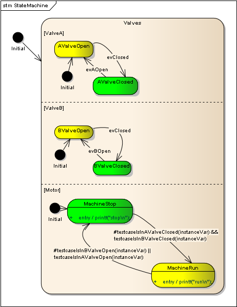
State diagrams follow the run-to-completion concept: Transitions that fire are fully executed and the state machine reaches a stable state configuration until it returns and can respond to the next event. To ensure this a copy of the instance data is kept and state changes are only performed on that copy. In practice this means that changes in one region does not influence other regions. Look into the following example. If the event evClosed is sent region ValveA and ValveB change state. But there is no state change in region Motor at the same time. The reason is that the transition from Stop → Run was not triggered at the beginning of the machine execution. This behavior ensures that the result of a machine execution step is 100% predictable and e.g. not independent of the execution order of regions.

And the conclusions?
Usually there is a way to model a problem with regions and without regions. The solution with regions allows to model a kind of parallelism and allows to explicitly display independent parts of a system.
On the other side exactly this parallelism is responsible that models with regions looks a bit more complex at first view.
If you have comments and suggestions please let me know! If you are interested to test this version download the latest beta following this download link.
~~DISCUSSION|Leave your comments~~


 Figure 1b: State machine model of a microwave oven using regions (created with EA).
==== Alternative design without using regions ====
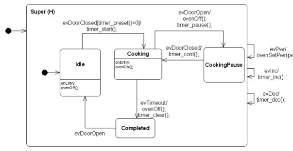
The microwave oven can also be modelled in a different way as shown below (the example is taken from the manual and code is available in the examples folder of the SinelaboreRT download). This model was created from an outside perspective not showing the state of different parts explicitly. It might be easier to follow the state flow during debugging and simulation because there is no parallelism. On the other hand the status of some
parts of the oven are not a visible as in the model with regions.
 Figure 2: Oven model not using regions.
==== How regions are implemented ====
The following brief descriptions explains how regions are implemented.
* For each region an own function is generated. Its name is automatically derived from the region name.
* If a state contains several regions they are called one after the other (in alphabetical order). If the event sent to the state machine was processed in one of the regions no further event handling happens. Otherwise the event is processed in the parent state. This is similar to the event handling of normal hierarchical state machines.
* To maintain consistency during execution of machine code a copy of the instance data is created at the beginning of the state machine code. All tests are performed on the original instance data. All changes are done on the copy. This ensures that all regions “see” the same situation when running. At the end of the machine code the modified instance data is copied back to the original data.
  Note: this is not yet available in the C