Table of Contents
Leader State Machine - Follower State Machines
Background
The Unified Modeling Language (UML) allows to model quite elaborate state machines especially when using concurrent regions (aka AND states or parallel states). Concurrent regions are a powerful design measure but also have its price.
Unexperienced users tend to create one big state diagram containing all parts (subsystems) of the system. Due to their own behavior and parallel execution subsystems must then be modeled as concurrent regions.
Read on to learn about an alternative solution.
Take a microwave oven as example. There is a lamp, motor and the microwave radiator itself all reacting on events. One approach is to create one big parent state and put the different parts of the oven in parallel regions.
Figure 1: Simplified oven model, designed with regions.
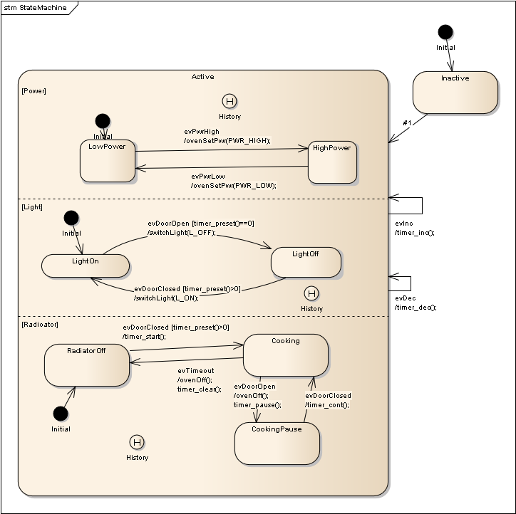
The key benefits of UML regions are:
- Unordered List Itemconcurrent regions allow to model parallelism.
- everything is shown on one page
The drawbacks are:
- The diagrams can become quite large. Our diagram just shows some states. Reality might be much more complex.
- As a direct consequence one has to scroll back and forth all the time when working on different parts of the model
- Refining behavior in concurrent regions makes the parent state containing the regions bigger and bigger. Depending on the modeling tool features’ this often has the consequence that a lot of work is going into moving states around to make space for new ones instead on focussing on the design work itself.
Alternative solution
To reduce the complexity good practice in engineering is to break down the problem into smaller pieces. In software this good approach means to put the subsystem state machines into their own state diagrams.
This has the benefit to create smaller diagrams dedicated to a specific subsystem e.g. the radiator. These diagrams can be developed, verified and validated separately without considering the whole system. Eventually from a different developer (deepening on project size).
As a consequence the state machines must be able to exchange events. Or at least one state machine (the leader) must be able to send events to the other state machines (the followers).
Lets take the microwave example again. Now the leader machine contains only the overall behavior. The radiator, lamp and other subsystems were modeled as follower state machines. They are controlled from the leader machine. E.g. if the main machine reaches cooking it sends the radiator an event to switch on radiation. On this top level we are not interested how the radiator subsystem works in detail. In reality it might be a complex state machine with many states dealing with the radiator electronics in the oven. But this is not relevant on the top level diagram.
The following figures show the leader machine and then two simplified examples of follower state machines.
Figure 2a: Leader machine. It just sends events to the followers to trigger actions. Note that also the leader might receive events from other state machines (e.g. the button subsystem). In one extreme shape there is not even a leader but only cooperating subsystems.
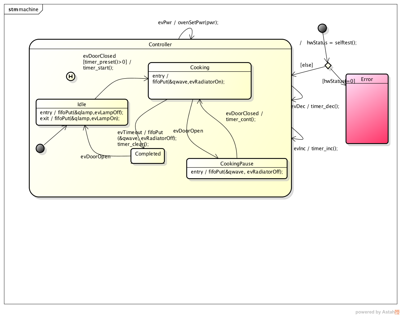
Figure 2b: Simplified lamp subsystem reacting on events from the leader (or from additional sources e.g. hardware triggered events or timer events).
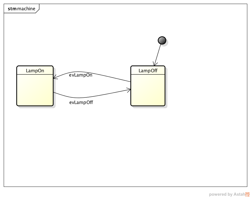
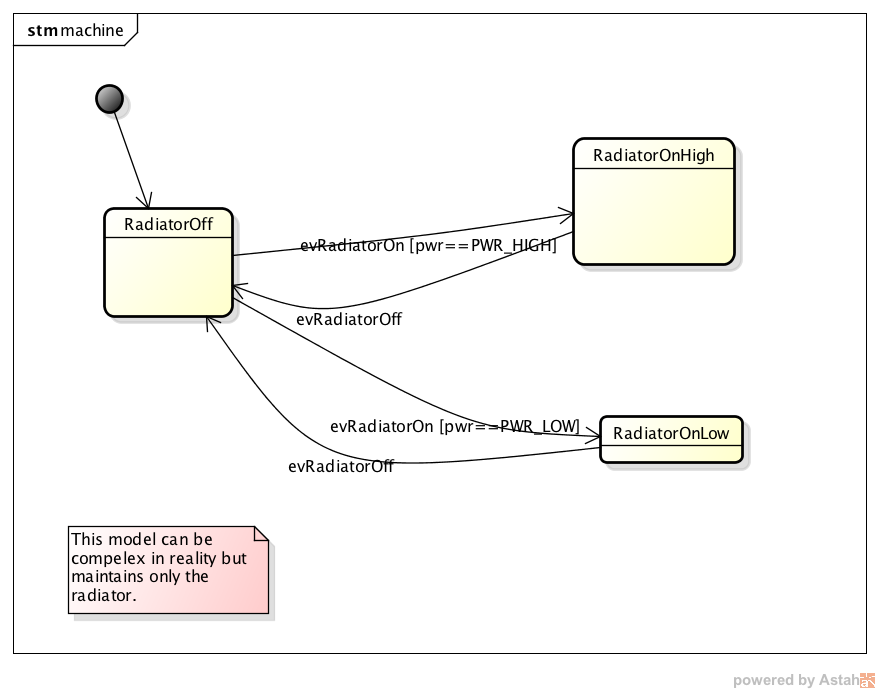
Figure 2c: Simplified radiator subsystem reacting on events from the leader (or from additional sources e.g. hardware triggered events or timer events).
Connecting state machines
For communication between state machines different solutions are available. What is actually used depends a lot on the overall system needs and system features e.g. with/without RTOS etc. On smaller systems binary flags might be sufficient. But usually a good solution is to use queues. Queues decouple the state machines and offer a clear interface to send and receive events. Event queues often have the feature to push events in front so high importance events can be processed first. A subsystem also might defer an event and put it into the queue again if it should be processed later. The subsystems might run in a separate thread (if an OS is present) or can be called from a main loop.
Conclusion
Separating a system into different subsystems running their own state machines is a well know design practice and helps to better keep complex developments under control.
Hope you enjoyed this article. Let me know your feedback!
Peter
~~DISCUSSION|Leave your comments~~